
Foam producing pump with anti-drip feature

a foam producing pump and anti-drip technology, applied in the field of foam producing pumps, can solve the problems of foam remaining on the nozzle and ultimately dripping off, add to the development and pump cost, and the problem is particularly acute, and achieve the effect of avoiding dripping

Inactive Publication Date: 2006-02-28
KANFER JOSEPH S
View PDF10 Cites 128 Cited by
  • Summary
  • Abstract
  • Description
  • Claims
  • Application Information

AI Technical Summary

Benefits of technology

[0010]The current invention employs a typical foam producing pump and adds an additional feature intended to dislodge the foam stream from the outlet so as to eliminating dripping.
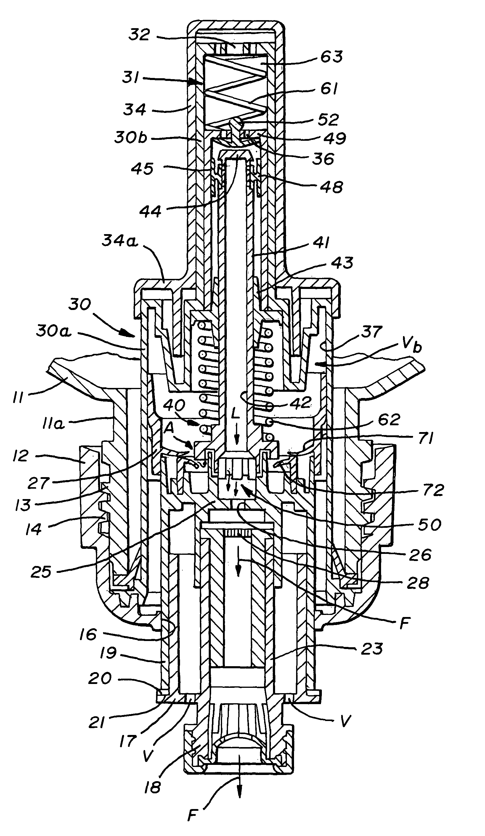
[0012]In furtherance of the principal object of this invention, it has been found that if the air pump is still moving when the liquid pump bottoms out, the foam is pushed out of the orifice by the air during the remainder of the stroke and is broken off from the orifice tip by a blast of air thereby eliminating the hanging foam on the outlet or nozzle and ultimately eliminating dripping.

Problems solved by technology

However, it is often the case that a residue of foam remains on the nozzle and ultimately drips off.
Such modifications, however, add to development and pump costs.
This problem is particularly acute when the container is inverted and the pumping action takes place from beneath the container.
In any event, when a foam producing pump is operated in this fashion the pump, after exhausting its normal liquid pumping or drawing function, does not fully exhaust the foam stream particularly at the outlet or nozzle of the pump so that some of the foam stream typically hangs on the outlet at the end of the stroke and eventually, of course, will revert to its liquid form and drip.
Dripping in pumps of this general nature and in pumps of this particular nature as well are objectionable because they are messy, unsightly and require maintenance to clean them up.

Method used


Image

  • Foam producing pump with anti-drip feature
  • Foam producing pump with anti-drip feature
  • Foam producing pump with anti-drip feature

Examples


Embodiment Construction

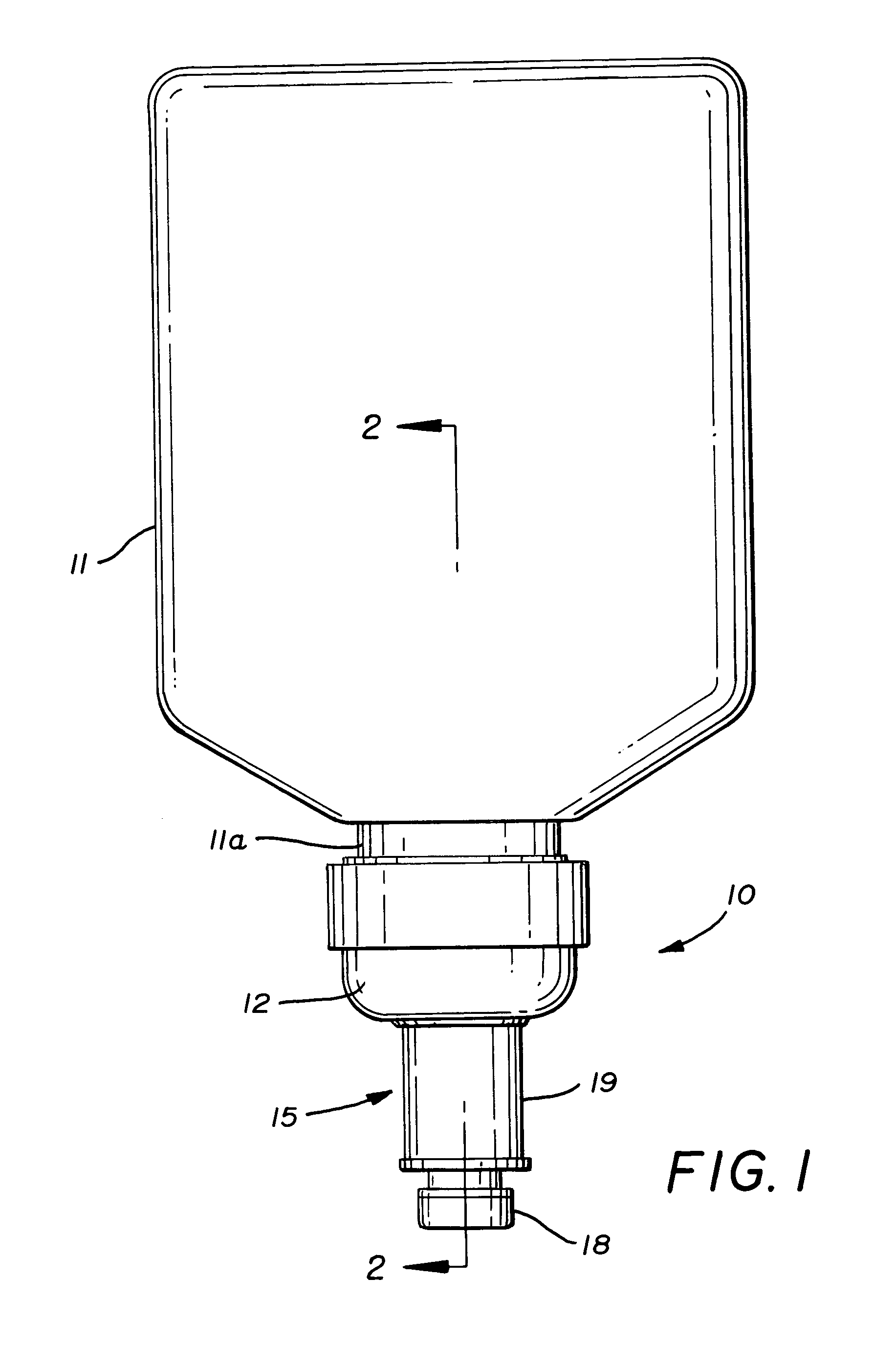
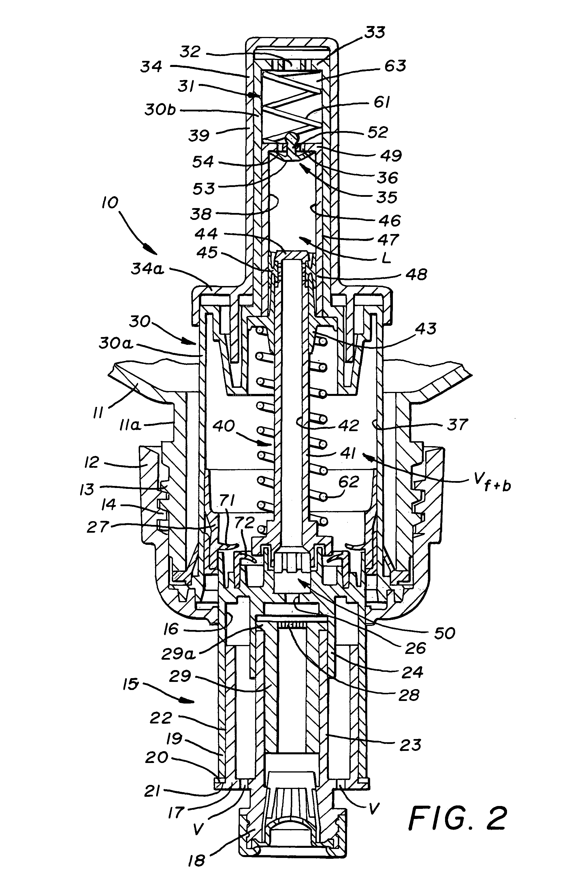
[0023]Referring first to FIG. 1 of the drawings, it will be seen that a pump, according to the concepts of the present invention and generally indicated by the numeral 10, is used in connection with a container 11. Container 11 may be of any type and a generic bottle-type container is shown for example purposes only. In the example, the container 11 and pump 10 are shown in a downward orientation, but the pump 10 is not limited to this orientation and may be inverted or otherwise displaced from the depicted orientation. In the example depicted in the figures, pump 10 is fastened to a neck portion 11a of container 11. A number of means of joining the pump 10 and container 11 may be used including, for example, threaded attachment of the pump 10 to the container 11, as shown in FIG. 2. To that end, a threaded collar 12 may be provided on pump 10 having internal threads 13 for attachment to external threads 14 formed on the neck portion 11a of container 11.

[0024]Pump 10 further include...


PUM


Abstract

A pump including a pump body having a head assembly slidably received therein; a mixing chamber in communication with an air source and a liquid source; wherein the head assembly is movable relative to the pump body to define a pump stroke, wherein the head assembly urges air from the air supply and liquid from the liquid supply into the mixing chamber to form a foam during the pump stroke; wherein the mixing chamber opens externally of the pump body and wherein during a portion of the stroke less than a complete stroke, the mixing chamber receives fluid and air to form a foam and discharge the foam externally of the pump and wherein during the remainder of the stroke, a blowing charge from the air source is urged through the mixing chamber and externally of the pump to evacuate any residual foam in the pump.

Description

RELATED PATENT APPLICATIONS[0001]None.FIELD OF THE INVENTION[0002]This invention relates, in general, to pumping devices and relates, in particular, to a pump capable of attachment to a container or reservoir, drawing material therefrom and converting a liquid material to a foam material by mixing it with air upon activation of the pump.BACKGROUND OF THE INVENTION[0003]It is well known to provide pumps which, when attached to a suitable reservoir of liquid, are capable, upon actuation of the pump, of expelling a foamed product from the outlet of the pump. Such pumps are well known and widely used to dispense a variety of products.[0004]In general, they operate by attaching a pump to the neck of a container which serves as a reservoir for the liquid material which can take many forms, such as, soaps, lotions, etc. These pumps operate so that upon actuation of the pump a predetermined amount of liquid is drawn from the container or reservoir, mixed with air and expelled through a nozz...

Claims


Application Information

Patent Timeline
Patent Type & Authority Patents(United States)
IPC IPC(8): B05B9/043
CPCB05B7/0037B05B11/3087B05B11/3021B05B11/0059B05B11/1021B05B11/1087
Inventor SAYERS, RICHARD C.
Owner KANFER JOSEPH S
Learn More