A 3D printing device with a rotary digital valve

A 3D printing, digital valve technology, applied in the field of rapid prototyping devices, can solve the problems of liquid dripping, restricting printing efficiency, affecting printing accuracy, etc. The effect of motor speed

Inactive Publication Date: 2016-09-07
FUZHOU UNIV
View PDF10 Cites 0 Cited by
  • Summary
  • Abstract
  • Description
  • Claims
  • Application Information

AI Technical Summary

Problems solved by technology

The current valve-controlled injection mainly adopts direct-acting on-off valves, which have a process of acceleration and deceleration of the valve core in each opening and closing cycle, and the opening and closing time is long; especially in the case of large flow rates, the opening and closing inertia force of the valve core is adversely affected more significantly, which seriously restricts the improvement of printing efficiency
[0005] 2) The reliability of valve-controlled injection decreases with the increase of output flow, and the increase of flow encounters a bottleneck
Under high-speed injection, the inertial impact of the large-mass spool forces the output pressure and flow to fluctuate, and the printing reliability decreases rapidly.
[0006] 3) Micro-liquid dripping easily occurs between two jets, which restricts high-quality printing
During the time when the first injection is completed and the second injection is not started, the liquid in the nozzle is prone to dripping under the action of gravity, which seriously affects the printing accuracy
The current valve-controlled jetting (such as the reference patent WO058373A2) lacks effective control of liquid dripping, which inhibits the further improvement of printing accuracy

Method used


Image

  • A 3D printing device with a rotary digital valve
  • A 3D printing device with a rotary digital valve
  • A 3D printing device with a rotary digital valve

Examples


Embodiment Construction

[0035] The present invention will be described in further detail below in conjunction with the accompanying drawings and specific embodiments.

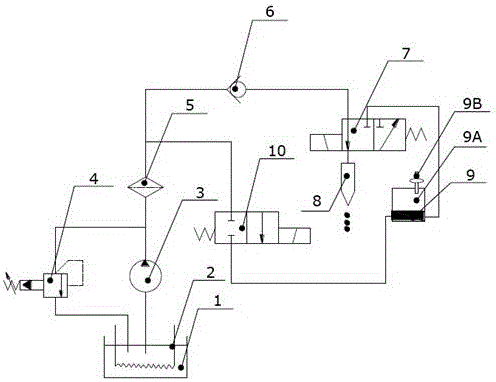
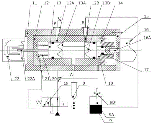
[0036] Such as figure 1 as shown, figure 1 It shows the overall structure of the embodiment of the present invention with the rotary digital valve 7 in the 3D printing injection system. In the system, materials are placed in the main material box 1 with a heating device 2 for heating to meet the spraying conditions. When the rotary digital valve 7 works in the left position, the material passes through the main material box 1, the pump 3, the filter 5, the one-way valve 6, the rotary digital valve 7, and then is ejected from the printing nozzle 8; the rotary digital valve 7 is the key component of the printing injection system. The output of discrete liquid is realized through the rotation of the valve core 13. During the working process of the injection system, in order to avoid the phenomenon of liquid dripping under the action of...


PUM


Abstract

The invention discloses a 3D printing device with a rotary digital valve. As the control element of the 3D printing injection system, the rotary digital valve is composed of valve core, valve sleeve, valve body and displacement sensor from the inside to the outside. There are periodically distributed notches on the two shoulders of the spool, and the corresponding valve sleeve surface is provided with feed holes and negative pressure holes corresponding to the spool; the spool is driven by a motor to rotate, combined with the feed hole The position change of the triangular groove symmetrical to the negative pressure hole and the valve core realizes periodic rapid on-off, thereby achieving high-frequency output of sprayed droplets. The device has a linkage back-suction structure, which can eliminate the phenomenon of liquid dripping due to gravity between two injections, and has high reliability. In addition, this rotary switch structure enables the output flow of sprayed droplets to increase rapidly with the high-speed rotation of the valve core, which is especially suitable for the field of industrial-grade rapid prototyping with high frequency response and large flow.

Description

technical field [0001] The invention relates to a device for rapid prototyping, in particular to a 3D printing device with a rotary digital valve. Background technique [0002] The current mainstream 3D printing technology realizes rapid manufacturing through layer-by-layer superposition and solidification of materials. During the single-layer printing process, the liquid material in the working chamber of the print head forms droplets under the action of an external driving force, and is ejected to the corresponding position at a certain frequency and rate. Therefore, stable, precise and fast droplet ejection is the key to ensure the quality of 3D printing. [0003] 3D droplet jetting mainly has three forms: thermal bubble type, piezoelectric type and valve-controlled type. The thermal bubble type (for example, refer to patent 200980159776.5) heats the liquid material to 300°C to generate steam bubbles, so that the material is extruded and separated at the nozzle; scope ...

Claims


Application Information

Patent Timeline
Patent Type & Authority Patents(China)
IPC IPC(8): B29C67/00
Inventor 陈晖吴强斌杨鸿艺梁红星杜恒
Owner FUZHOU UNIV
Why Eureka
Try Eureka