Concrete void former

a void former and concrete technology, applied in sidewalk pavings, ground pavings, ways, etc., can solve the problems of difficult to remove difficult to pull void formers from concrete, etc., and achieve the effect of facilitating the removal of void formers

Inactive Publication Date: 2006-02-28
DAYTON SUPERIOR CORP
View PDF28 Cites 52 Cited by
  • Summary
  • Abstract
  • Description
  • Claims
  • Application Information

AI Technical Summary

Benefits of technology

[0005]The present invention provides a void former for creating flat-shaped voids in concrete slabs. The void former comprises a core assembly having at least two body members that are removably coupled together to define the desired void shape. The body members contact one another along confronting tapered surfaces, whereby separation of individual body members from the core assembly may be accomplished by sliding movement along the tapered surfaces. Advantageously, the body members may be successively removed from the void, once the concrete slab has sufficiently cured, to make removal of the void former easier.

Problems solved by technology

A drawback of previous methods and apparatus for forming voids in slabs is that it is very difficult to remove the void formers from the concrete after the concrete has cured.
This is due primarily to the surface adhesion between the concrete and the void former and is particularly problematic for void formers used to create flat-shaped slots in concrete slabs for receiving load plates.
Even when void formers are made from plastic, which does not bond to the concrete, surface adhesion between the concrete and the void former makes it difficult to pull the void former from the concrete.

Method used


Image

  • Concrete void former
  • Concrete void former
  • Concrete void former

Examples


Embodiment Construction

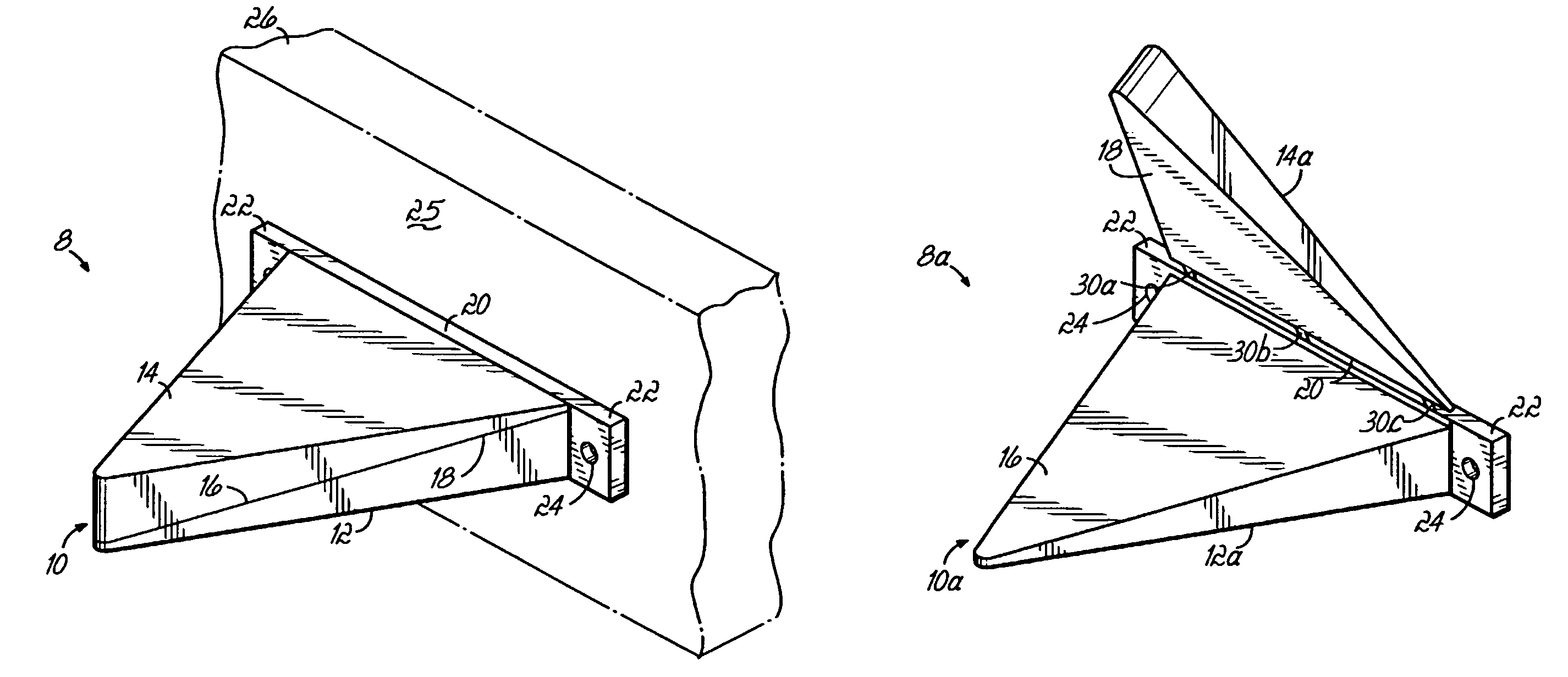
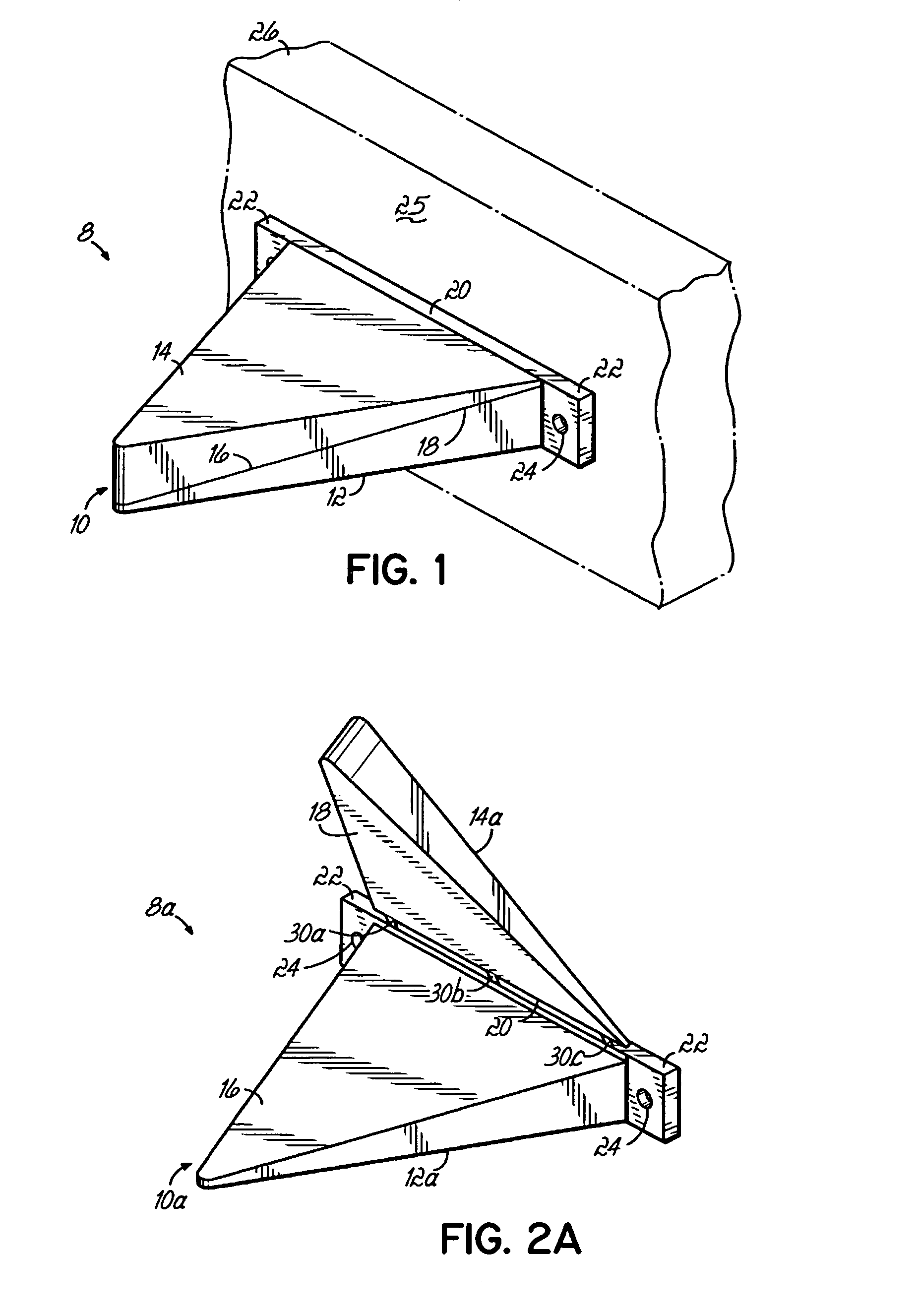
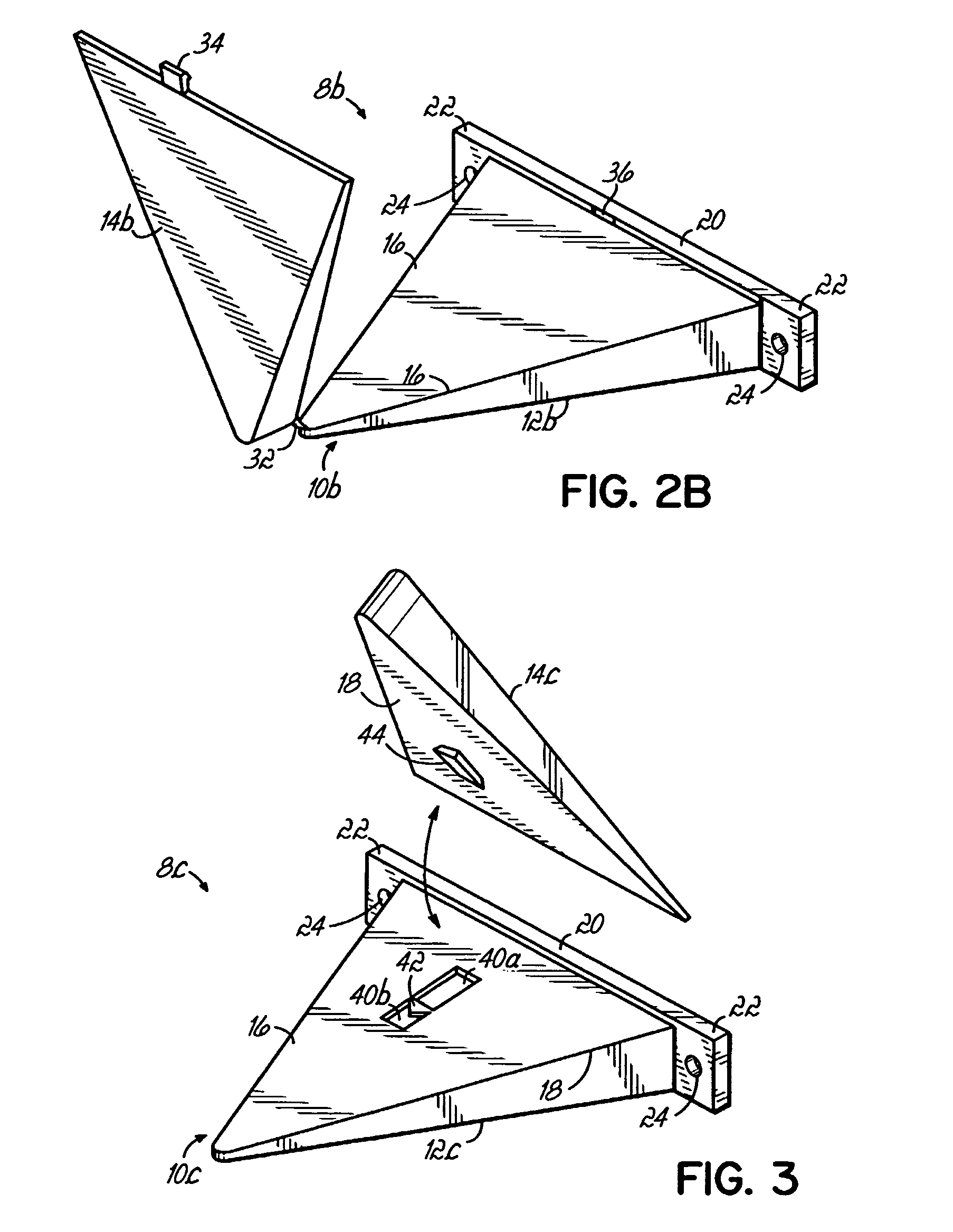
[0017]Referring to FIG. 1, there is shown an exemplary void former 8 of the present invention. The void former 8 comprises a core assembly 10 having first and second core body members 12, 14 removably coupled together to define a shape that will form a void in a concrete slab. In the exemplary embodiment shown, the core assembly 10 has the general shape of a triangular prism, wherein the first and second body members 12, 14 comprise adjacent truncated triangular prisms that engage one another along respective tapered surfaces 16, 18 to create the triangular prism shape. It will be recognized, however, that core assembly 10 may have other shapes suitable for forming a generally flat slot in a concrete slab. In the exemplary embodiment shown, the core assembly 10 further includes an attachment member 20 coupled to first body member 12. The attachment member 20 has first and second flanges 22 disposed proximate opposed ends of the attachment member 20, each flange 22 having apertures 2...


PUM

PropertyMeasurementUnit
shapeaaaaaaaaaa
surface adhesionaaaaaaaaaa
adhesionaaaaaaaaaa

Abstract

A void former comprises a core assembly having at least two body members. The body members are removably coupled together to define the desired shape of a void to be formed in a concrete slab. After the void has been formed in the concrete slab, the body members may be selectively removed from the void.

Description

FIELD OF THE INVENTION[0001]The present invention pertains to the construction of concrete slabs, and more particularly to a device for creating a flat void in a concrete slab.BACKGROUND OF THE INVENTION[0002]In the construction of flat concrete surfaces, such as aircraft runways, taxiways, parking aprons, and other concrete structures it is common to divide the surface into a number of individual slabs that are separated by expansion joints. Adjacent slabs are typically coupled to one another by dowels that extend across the expansion joints. The dowels help to transfer loads between adjacent slabs and to control relative movement of the slabs. Conventional concrete dowels have been provided as elongate metal rods or flat metal plates. Regardless of whether rods or plates are used as dowels, a void must be formed in each concrete slab to receive a portion of the dowel. Such voids are typically formed in wet concrete, either at the time of pour, by attaching void formers to the inne...

Claims


Application Information

Patent Timeline
Patent Type & Authority Patents(United States)
IPC IPC(8): B28B7/28B28B7/16E01C11/14
CPCE01C11/14
Inventor BENNETT, CLIFFORD D.
Owner DAYTON SUPERIOR CORP
Why Eureka
Try Eureka