Engine speed limiter for a hoist

a technology of speed limiter and hoist, which is applied in the direction of hoisting equipment, wellbore/well accessories, drilling pipes, etc., can solve the problems of excessive power delivery, damage to the hoist itself, and broken well components, etc., to limit or reduce the lifting force of the hoist, limit or reduce the rate of fuel consumption of the engine, the effect of limiting or reducing the lifting for

Inactive Publication Date: 2006-02-28
KEY ENERGY SERVICES
View PDF25 Cites 20 Cited by
  • Summary
  • Abstract
  • Description
  • Claims
  • Application Information

AI Technical Summary

Benefits of technology

[0019]Another object of some embodiments is to limit or reduce the lifting force of a hoist by limiting or reducing an engine's rate of fuel consumption.
[0020]One or more of these and other objects of the invention are provided by a mobile service rig that includes an engine-powered hoist. The lifting force of the hoist is limited or reduced in response to reaching a predetermined lifting force. The lifting force can be limited or reduced by limiting or reducing the speed of the engine.

Problems solved by technology

As a result, accidents may occur when excessive power is delivered to a load.
Not only can various well components be broken, but also the hoist itself can be damaged.
Exceeding the rated capacity of the hoist can lead to catastrophic results.

Method used


Image

  • Engine speed limiter for a hoist
  • Engine speed limiter for a hoist
  • Engine speed limiter for a hoist

Examples


Embodiment Construction

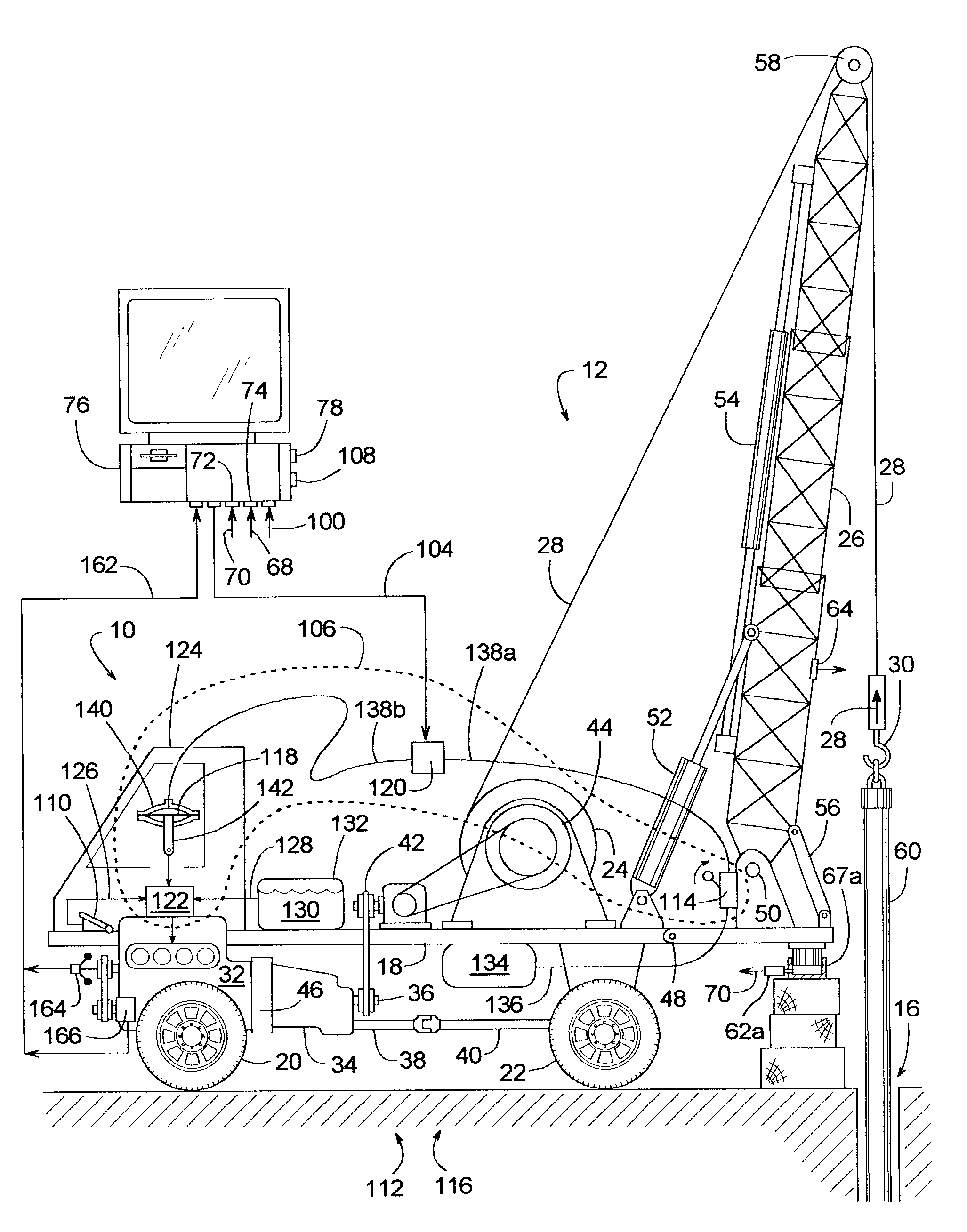
[0032]When operating a hoist of a mobile service rig, accidents can be avoided by limiting the hoist's engine speed in response sensing that the hook load of the hoist has reached a predetermined limit.

[0033]One example of a mobile service rig 10 with a hoist 12 for exerting an upward force 14 that varies while servicing a well 16 is schematically illustrated in FIG. 1. In this example, service rig 10 is a vehicle that includes a truck frame 18, a drive wheel 20 and / or 22 coupled to frame 18 for propelling rig 10 along a road, a hoist drum 24 supported by frame 18, a derrick 26 coupled to frame 18, a hoist cable 28 supported by derrick 26 and spooled about drum 24, a block 30 suspended from cable 28 (block 30 can be a hook or some other device that transmits force 14 to cable 28), an internal combustion engine 32 supported by frame 18, and a transmission 34 that couples engine 32 to hoist drum 24 and drive wheel 22.

[0034]To drive either hoist drum 24 or drive wheel 22, transmission ...


PUM


Abstract

A mobile service rig for wells includes a hoist powered by an internal combustion engine. In response to the hoist exerting a predetermined lifting force, the lifting force is limited by automatically limiting or reducing the speed of the engine.

Description

BACKGROUND OF THE INVENTION[0001]1. Field of the Invention[0002]The subject invention generally pertains to mobile service rigs for wells and more specifically to a mobile service rig that includes an engine powering a hoist.[0003]2. Description of Related Art[0004]Oil wells and wells for other fluids typically include a well casing, tubing, sucker rods and a reciprocating drive unit. A well casing is what lines the well bore and usually comprises a long string of relatively large diameter pipe interconnected by threaded couplings known as collars. Casings generally define the overall diameter and depth of a well bore. Well tubing typically comprises a long string of pipe sections whose threaded ends are also interconnected by threaded couplings. The tubing extends down through the casing and provides a conduit for conveying oil or some other fluid to the surface of the well. A submerged reciprocating pump attached to the lower end of the tubing draws the fluid from the annulus betw...

Claims


Application Information

Patent Timeline
Patent Type & Authority Patents(United States)
IPC IPC(8): B66D1/00B66D1/58E21B7/02E21B19/00E21B41/00
CPCB66D1/58E21B41/0021E21B19/008E21B7/022
Inventor NEWMAN, FREDERIC M.
Owner KEY ENERGY SERVICES
Why Eureka
Try Eureka