Radial lip seal

a lip seal and radial technology, applied in the direction of engine seals, piston rings, mechanical equipment, etc., can solve the problems of substantial leakage between the the circumferential surface, smooth outer side of the lip, and lack of sealing function

Active Publication Date: 2006-02-28
GM GLOBAL TECH OPERATIONS LLC +1
View PDF8 Cites 44 Cited by
  • Summary
  • Abstract
  • Description
  • Claims
  • Application Information

AI Technical Summary

Benefits of technology

[0007]A pair of dust seals extend from the annular support. A first dust seal is spaced axially from the seal lip and positioned to closely oppose the circumferential surface of the shaft. A second dust seal spaced radially from the first dust seal is positioned to closely oppose a radial surface of an associated flywheel. The dust seals limit the entry of particles into the oil seal lip, thereby extending the operating life of the oil seal.

Problems solved by technology

An outer side of the lip is smooth and does not provide a sealing function when the seal is properly installed.
The varied diameter creates a substantial leak between the outer side of the lip and the circumferential surface.

Method used


Image

  • Radial lip seal
  • Radial lip seal
  • Radial lip seal

Examples


Embodiment Construction

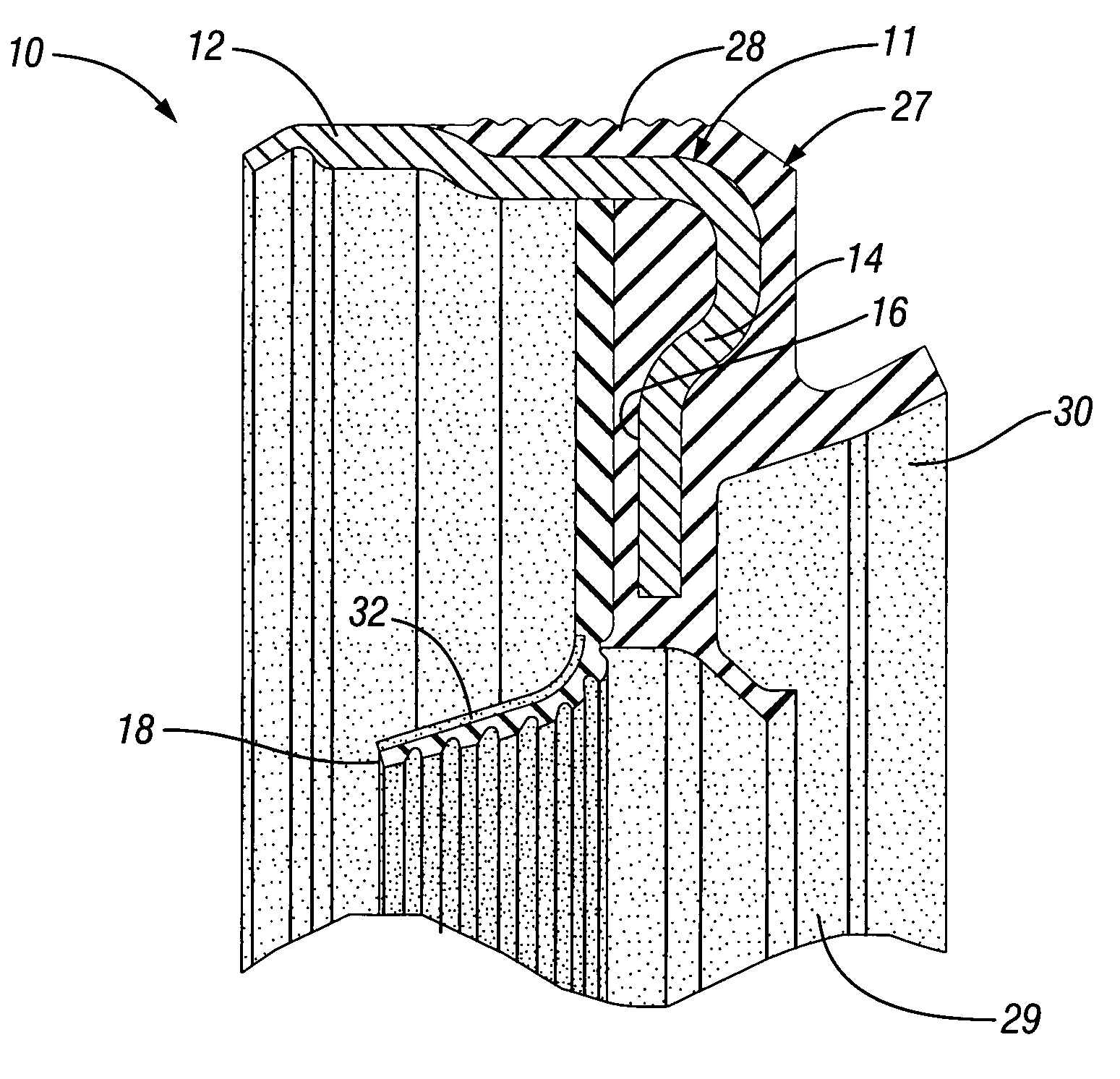
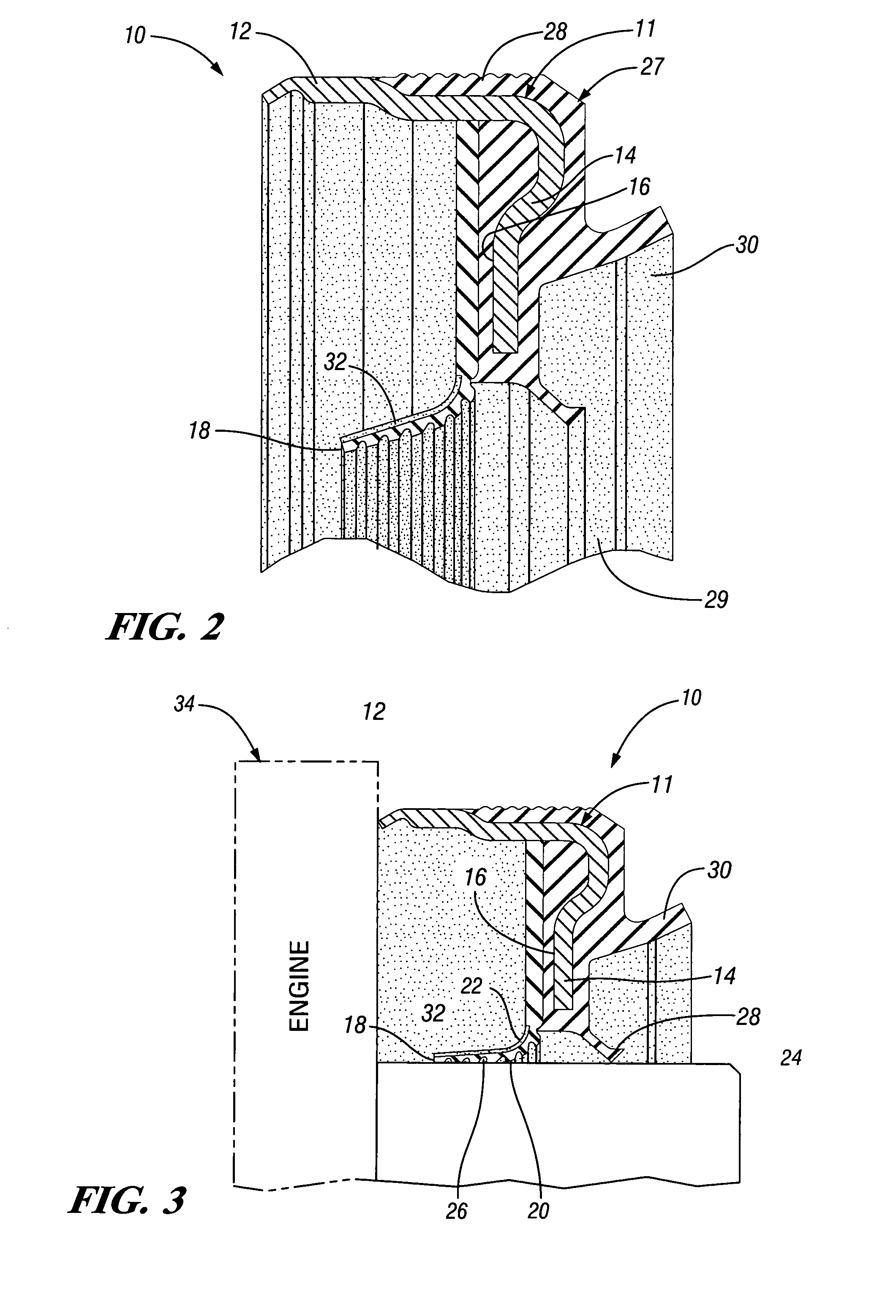
[0018]Referring now to FIGS. 1 and 2 of the drawings in detail, numeral 10 generally indicates a radial lip seal for use in automotive engine applications. The seal 10 includes a steel support ring 11 having a generally cylindrical outer portion 12, connecting at one edge with a radial portion 14 extending inwardly to an inner periphery 16. An annular seal lip 18 formed of elastomeric material such as polytetrafluoroethylene is connected to the inner periphery 16 and extends both axially and radially inward while the seal is in a free state, as shown in FIG. 2. The lip 18 has an inner side 20 and an outer side 22. The inner side 20 is designed to seal a circumferential surface of a shaft 24, as shown in FIG. 3 and may have hydrodynamic aids 26 such as grooves, flutes, ribs, or threads. These operate to create a fluid pressure differential for pumping fluid away from the end of the lip 18.

[0019]The radial lip seal 10 preferably has a rubber body 27 overmolded on portions of the annul...


PUM


Abstract

A radial lip seal including an annular support with a radially extending portion having an inner periphery. An annular seal lip formed of elastomeric material such as polytetrafluoroethylene is connected to the inner periphery. The lip has an inner side adapted to seal a circumferential surface of a shaft and an outer side. The outer side of the lip has a plurality of grooves or protrusions to vary the diameter of the lip. The varied diameter creates a substantial leak between the outer side of the lip and the circumferential surface. The leak created is sufficient to be detected by a low-pressure air test.

Description

TECHNICAL FIELD[0001]This invention relates to a radial lip seal for sealing a relatively rotatable cylindrical member. The invention has particular utility in the automotive industry for engine crankshaft seals.BACKGROUND OF THE INVENTION[0002]Radial lip seals or radial contact seals are used to seal a shaft's circumferential surface by engagement of a lip with the surface to be sealed. In some cases, helical grooves in the engaging surface of the seal are provided to respond to shaft rotation by pumping the oil or other fluid back toward the oil sump to minimize leakage.[0003]In order to provide an adequate seal, the radial lip seal must be installed so that the lip is angled axially inward toward the sump and stretched over the shaft with the helical grooves engaging the circumferential surface. However, during installation it is possible for the radial lip to be folded (flipped) over to at least a partially extend outward away from the oil sump with the back of the lip engaging ...

Claims


Application Information

Patent Timeline
Patent Type & Authority Patents(United States)
IPC IPC(8): F16J15/32
CPCF16J15/3228F16J15/3296F16J15/3268F16J15/3244
Inventor BRYDE, STEVEN G.CHRISTENSEN, TERRENCETEIXEIRA, MARCOS BASILELIMA, MARCIO CALDAS CAMARGOMACHADO, ANTONIO RANGELSANTANNA, MARCOS CASTANHO
Owner GM GLOBAL TECH OPERATIONS LLC
Why Eureka
Try Eureka