Cord management device

a technology of electronic devices and management devices, applied in the direction of coupling device connections, applications, furniture parts, etc., can solve the problems of creating eyesores and hazardous home or workplace conditions, and achieve the effect of improving home and workplace safety and improving aesthetics

Inactive Publication Date: 2006-02-28
BLOOMIN PARTNERS A TEXAS CORP
View PDF13 Cites 50 Cited by
  • Summary
  • Abstract
  • Description
  • Claims
  • Application Information

AI Technical Summary

Benefits of technology

[0004]In accordance with the present invention, the disadvantages and problems associated with supplying power and various forms of electronic signals to electronic devices have been substantially reduced or eliminated. In particular, a cord management device is provided.
[0007]Important technical advantages of certain embodiments of the present invention include improving home and workplace safety, providing a surge-protector with improved aesthetic qualities, and offering an effective system for notifying users of the current status of surge-protection features. Other technical advantages of the present invention will be readily apparent to one skilled in the art from the following figures, descriptions, and claims. Moreover, while specific advantages have been enumerated above, various embodiments may include all, some, or none of the enumerated advantages.

Problems solved by technology

As the number of components in a given system increases, the power cords and other cords associated with the various components can produce difficulties for a user attempting to locate and free the cord associated with a particular component, cause hazardous home or workplace conditions, and create an eyesore.

Method used


Image

  • Cord management device
  • Cord management device
  • Cord management device

Examples


Embodiment Construction

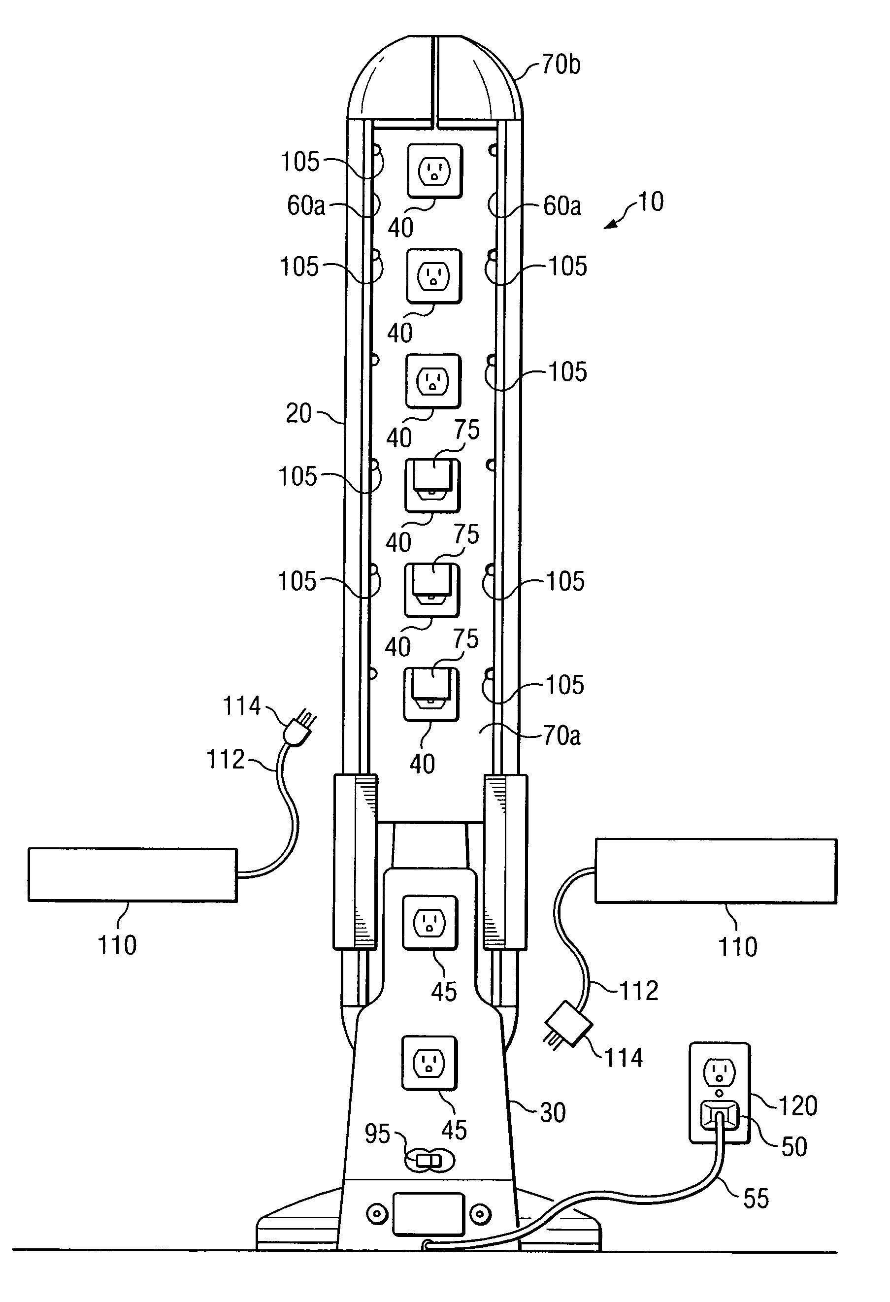
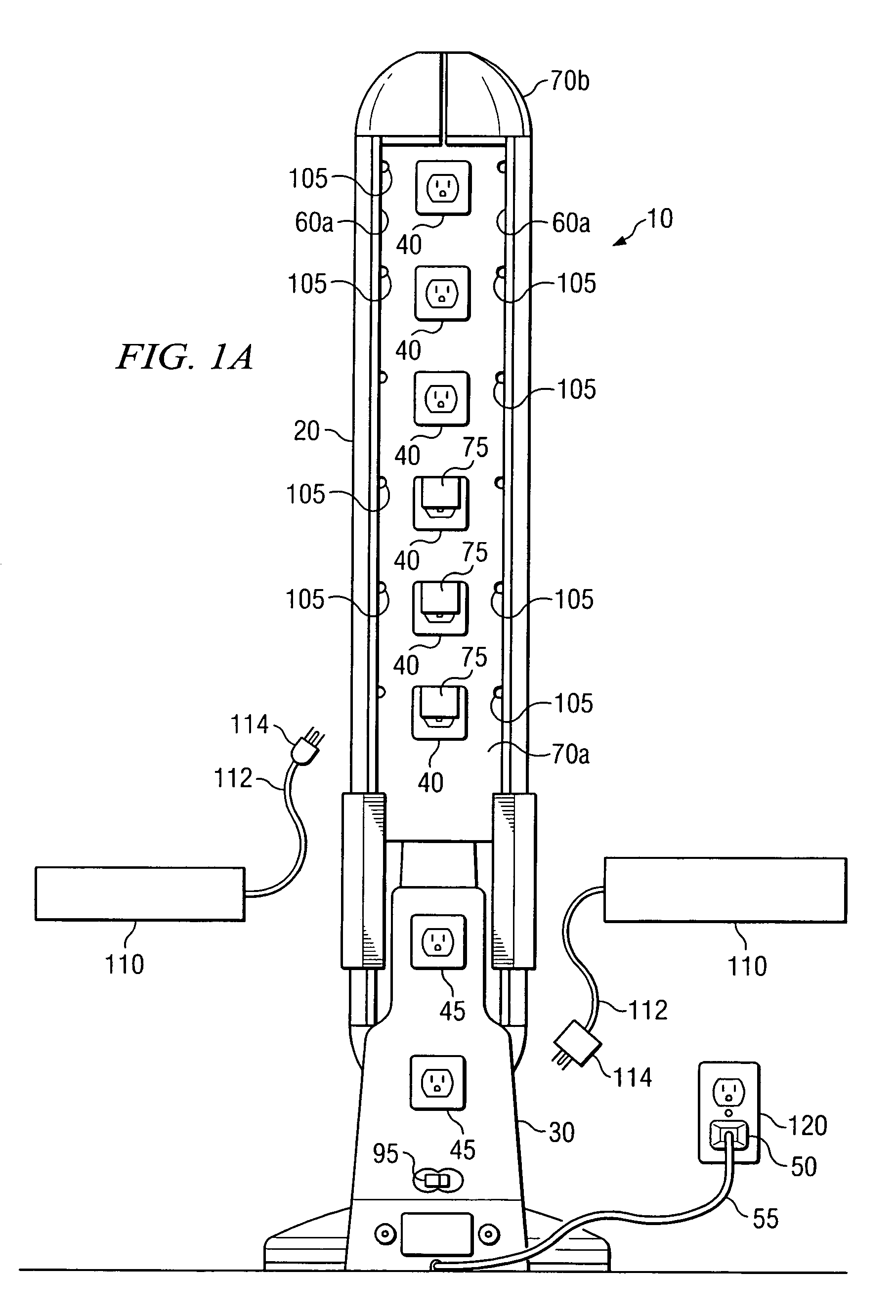
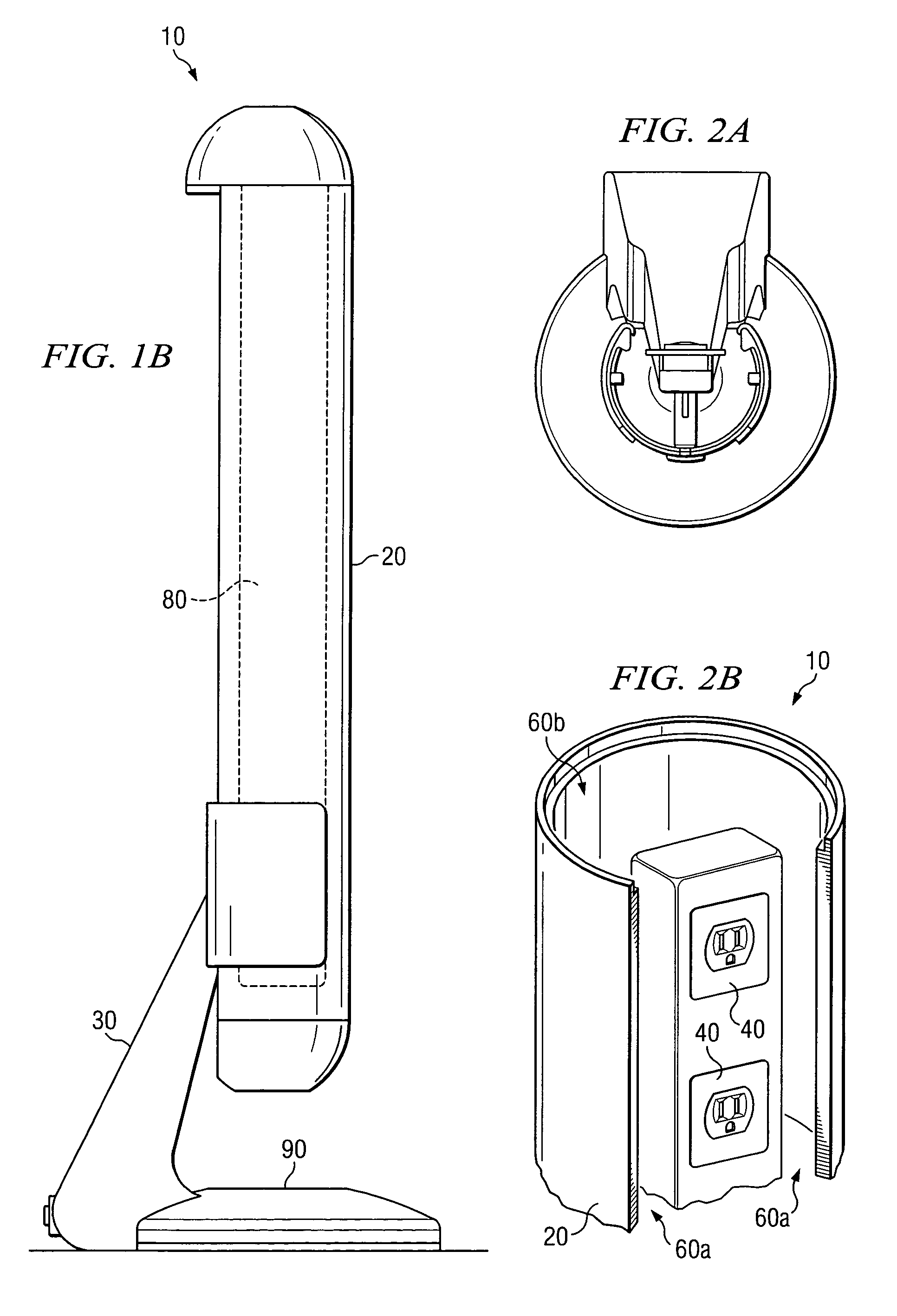
[0015]FIGS. 1A–1B illustrate, from numerous perspectives, a cord management device 10 according to a particular embodiment. FIGS. 1A and 1B provide a front and a side view, respectively, of cord management device 10. In the illustrated embodiment, cord management device 10 includes frame 20, base 30, a plurality of outlets 40, one or more brick outlets 45, a plug 50, one or more cavity openings 60, one or more cavity covers 70, safety tabs 75, a status indicator 90, and a switch 95. FIG. 1A additionally shows electronic devices 110 and external power supply 120. Cord management device 10 provides electricity from external power supply 120 to electronic devices 110 plugged into outlets 40. Additionally, cord management device 10 is capable of storing cords associated with electronic devices 110 plugged into outlets 40 within a cavity 80 of cord management device 10, represented by a dotted-line outline in FIG. 1B.

[0016]Frame 20 holds outlets 40 and other components of cord management...


PUM


Abstract

A device for providing electricity includes a frame, an outlet, a plug, and a cavity cover. The outlet is capable of providing electricity to devices plugged into the outlet. The plug is operable to provide electricity to the outlet from an external power source. The frame forms a cavity that is capable of storing a cord. Additionally, the cavity cover is capable of allowing access to the cavity through a cavity opening when a force is applied to the cavity cover and covering the cavity opening when the force is removed from the cavity cover.

Description

CROSS REFERENCE TO RELATED APPLICATION[0001]This application is a continuation of pending U.S. patent application Ser. No. 10 / 937,463, filed Sep. 8, 2004 and entitled “Cord Management Device.”TECHNICAL FIELD OF THE INVENTION[0002]This invention relates in general to consumer electronic devices, and more particularly, to a cord management system for electronic devices.BACKGROUND OF THE INVENTION[0003]In recent years, rapid growth in the number of electronic devices available in the consumer market, increased automation of the industrial sector, and the emergence of electronic information processing and storage in many areas of the business world has introduced a multitude of new electronic devices to the home and workplace. This in turn has led to a growing reliance on systems that utilize or include multiple electronic components. As the number of components in a given system increases, the power cords and other cords associated with the various components can produce difficulties f...

Claims


Application Information

Patent Timeline
Patent Type & Authority Patents(United States)
IPC IPC(8): H01R13/72
CPCH01R13/72A47B2200/0081
Inventor BLOOM, SAM A.GERARD, CHRISTIAN O.LEVERIDGE, PHILIP
Owner BLOOMIN PARTNERS A TEXAS CORP
Why Eureka
Try Eureka