Piston and method of manufacture

a technology of piston and manufacturing method, applied in the direction of manufacturing tools, soldering apparatus, electric/magnetic/electromagnetic heating, etc., can solve the problems of not being used, and achieve the effects of high integrity, low cost, and precise, uniform and controlled heating of surfaces

Inactive Publication Date: 2006-02-28
FEDERAL MOGUL WORLD WIDE LLC
View PDF38 Cites 32 Cited by
  • Summary
  • Abstract
  • Description
  • Claims
  • Application Information

AI Technical Summary

Benefits of technology

[0003]U.S. Pat. No. 5,150,517 is an example of friction welding, whereas U.S. Pat. No. 6,291,806 is an example of typical induction heating wherein the coils are presented to the sides of the contacting joining surfaces to induce energy and thus heat at the interface. Such side presentation of the induction coils has a tendency to heat the regions of the joining surfaces near the edges of the material adjacent the induction coils at a faster rate than those regions further from the coils, thus producing a variation in the heat flow and heat affected zone in the area of the material adjacent the interface. In a demanding, highly loaded application such as pistons for diesel engines, it would be desirable to provide a weld joint that is uniform in its heat affected zone across the interface so as to minimize any variation in strength and integrity of the material.
[0014]Another advantage of induction heating according to the invention is that it requires relatively low compression force to join the parts following induction heating as compared to friction welding in which the heat needed for welding is generated by relative rotation of the parts while under relatively high compression loads (about 1,000 psi vs. 20,000 psi for friction welding). Consequently, the fixturing and equipment needed to hold and support the parts for induction welding according to the invention need not be as substantial as that required for friction welding. Moreover, the architecture of the piston is liberated somewhat since the structure does not have to withstand the heavy compression loading which is imparted during friction welding and which often exceeds the loading experienced during use of the piston. Consequently, thinner sections and lighter weight pistons are possible with induction welding at a cost savings to the manufacturer and recognized fuel and emission efficiencies by the user of such pistons.

Problems solved by technology

It will be appreciated that such an architecture would present a challenge to joining the portions by induction welding, since access to the regions where the joining surfaces are located is limited and, in the case of the internal cooling gallery, inaccessible to the positioning of any induction coil next to the mated joining surfaces.
Based on the known existing technology in the field of pistons, a suitable technique for induction welding such complex architectures of pistons as those shown in the aforementioned '642 patent is not known to be in existence, and certainly is not known to be used due to the practical difficulties in adapting such induction heating technology to complex piston designs with multiple radially spaced joining surfaces.

Method used


Image

  • Piston and method of manufacture
  • Piston and method of manufacture
  • Piston and method of manufacture

Examples


Embodiment Construction

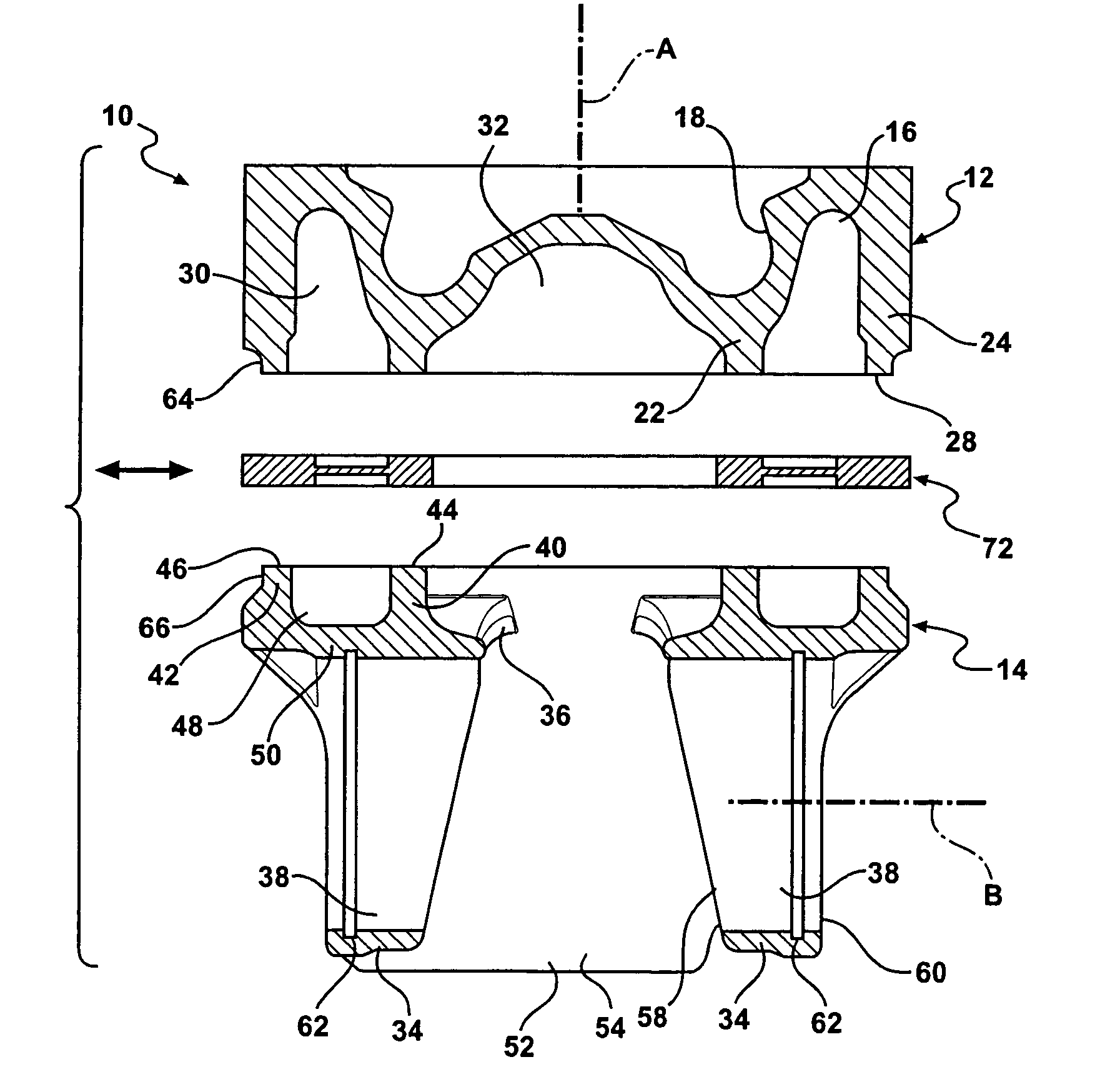
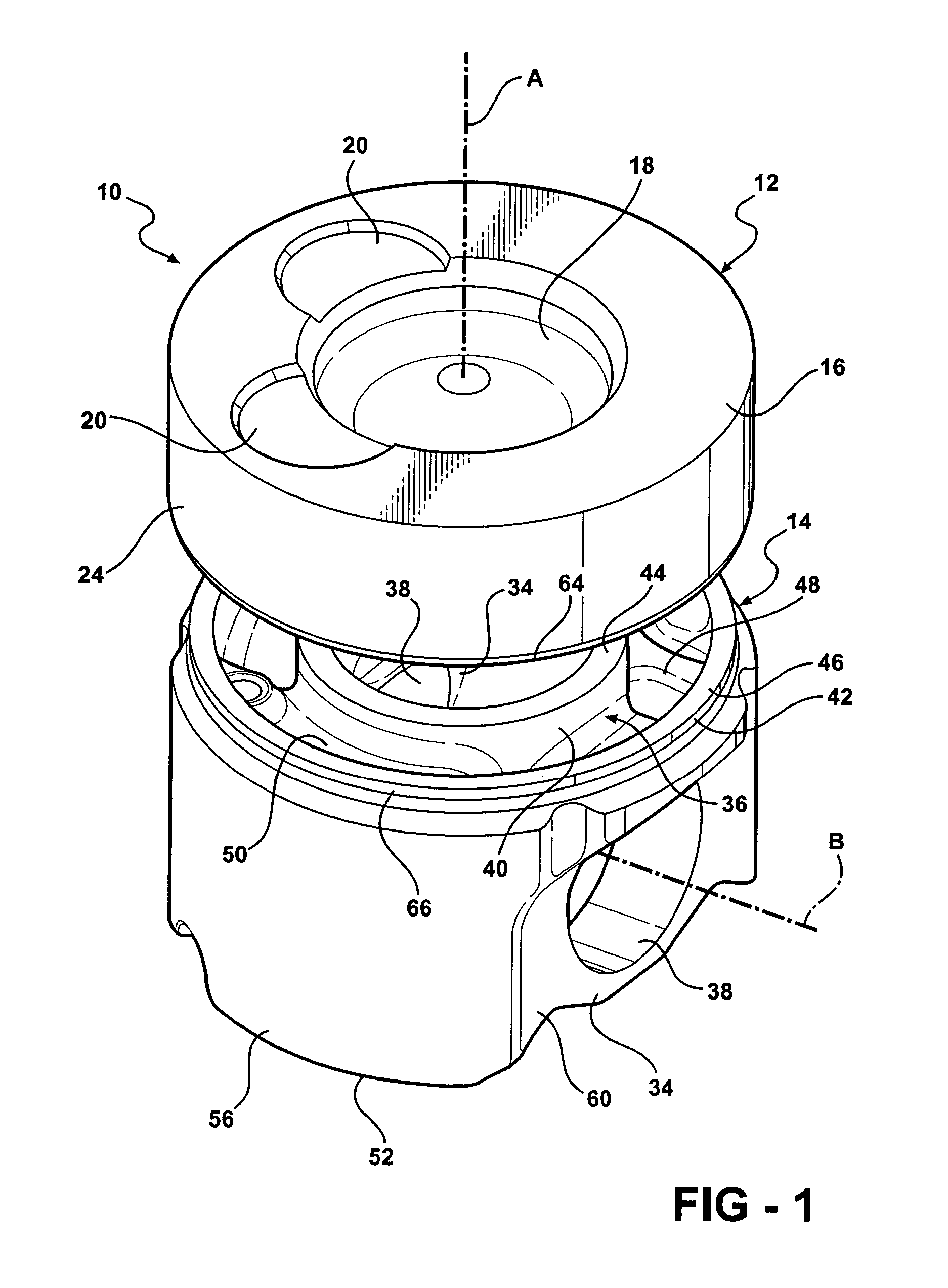
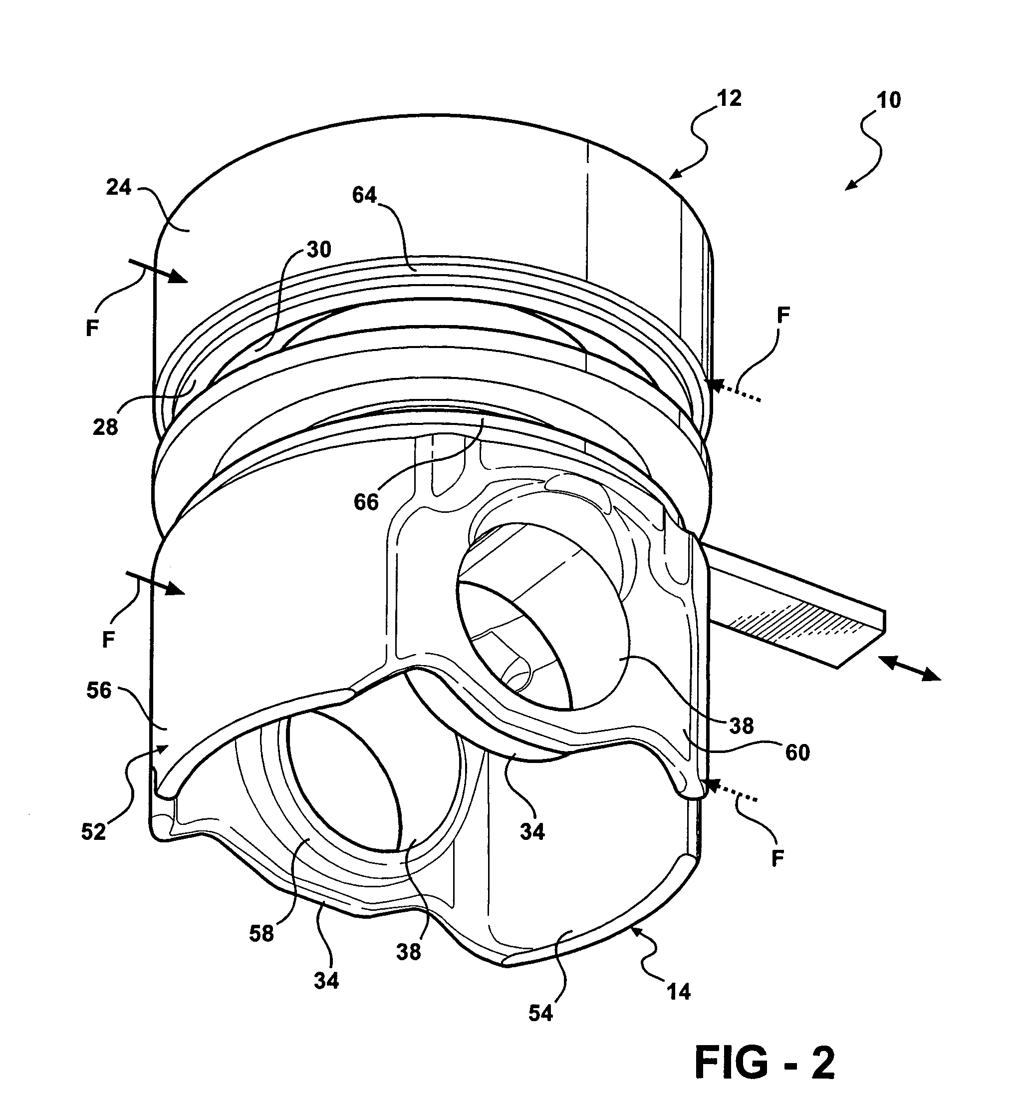
[0026]A piston constructed according to a presently preferred embodiment of the invention is shown generally at 10 in the drawings and is fabricated of at least two parts which are formed separately from one another in a manner to provide at least one and preferably at least two sets of circumferentially extending mateable joining surfaces which are initially spaced apart from one another and heated to a temperature sufficient for welding the parts, after which the heating of the surfaces is terminated and the surfaces joined to one another to effect a permanent weld between the parts.

[0027]In the illustrated embodiment, the piston 10 includes a first part 12 and a second part 14. Both parts 12, 14 are fabricated of metal, and preferably steel alloys, although the invention is not limited to these materials. The first and second parts may be cast, forged, fabricated of powder metal or any other process for making metal parts. The alloys used for the first and second parts 12, 14 may...


PUM

PropertyMeasurementUnit
bonding temperatureaaaaaaaaaa
temperatureaaaaaaaaaa
thicknessaaaaaaaaaa

Abstract

A piston particularly adapted for heavy-duty diesel engine applications is fabricated from separate parts having circumferentially extending joining surfaces that are heated prior to bonding to an elevated temperature sufficient to enable bonding of the joining surfaces, and thereafter the joining surfaces brought into contact with one another and twisted to attain a permanent metallurgical weld at the interface of the joining surfaces. The piston has radially spaced walls which are both welded simultaneously. The weld joints may lie in the same or different planes. Once joined, and while still hot, the parts may be pulled apart slightly to reduce the wall thicknesses at the weld joint.

Description

BACKGROUND OF THE INVENTION[0001]This application is a continuation-in-part of application Ser. No. 10 / 701,274, filed Nov. 4, 2003, now U.S. Pat. No. 6,825,450.[0002]Various methods are known for bonding separately formed portions of a piston in order to yield a piston structure. One such process is friction welding in which one portion of the piston is rotated at high speed while pressed against the other portion, with the resulting frictional energy generating sufficient heat to bond the portions together. Other techniques include resistance welding, induction welding, and the like in which, after the portions are brought into contact with one another, an energy flux is introduced across their joining surfaces which causes them to be heated sufficiently to join the surfaces to one another.[0003]U.S. Pat. No. 5,150,517 is an example of friction welding, whereas U.S. Pat. No. 6,291,806 is an example of typical induction heating wherein the coils are presented to the sides of the con...

Claims


Application Information

Patent Timeline
Patent Type & Authority Patents(United States)
IPC IPC(8): H05B6/10B23K1/002B23K13/01F01B31/08F02B3/06F02F3/00H05B6/02
CPCF02F3/003F02B3/06F02F2003/0061
Inventor RIBEIRO, CARMOEGERER, THOMASGAISER, RANDALL
Owner FEDERAL MOGUL WORLD WIDE LLC
Why Eureka
Try Eureka