Motor controller

a technology of motor controller and control system, which is applied in the direction of motor/generator/converter stopper, dynamo-electric gear control, motor/generator/converter stopper, etc., can solve the problem that the rotation frequency f of the coasting induction motor cannot be detected with a high degree of accuracy

Inactive Publication Date: 2006-02-28
MITSUBISHI ELECTRIC CORP
View PDF8 Cites 20 Cited by
  • Summary
  • Abstract
  • Description
  • Claims
  • Application Information

AI Technical Summary

Benefits of technology

[0014]a phase-reversal-timing detecting means for detecting as a phase-reversal timing a specific phase at which an amplification factor of ripple components superposed on the d-axis component of the 2-phase voltage command outputted from the d-axis current control means is maximal. Because the current phase commanding means turns a current-commanding phase by 180 degrees according to the specific phase outputted from the phase-reversal-timing detecting means, the rotating frequency F of the coasting induction motor can be detected with a high degree of accuracy.
[0015]In restarting after an instantaneous power failure being restored, after the current control has been started and the effect of transient variation has been abated, the phase-reversal-timing detecting means detects a first maximal value, a first minimal value, and a second maximal value by comparing a value of the integration term of the d-axis component of the 2-phase-voltage command outputted from the d-axis current control means with its previous value, and then outputs a time at which the integration-term value of the d-axis component of the 2-phase-voltage command becomes below (the first minimal value1+the second maximal value) / 2, as a first specific phase at which the current-commanding phase is turned by 180 degrees, to the current phase commanding means; therefore, the specific phase Tθ1 can be detected without being affected by the rotating direction of a coasting induction motor.
[0016]After outputting the first specific phase, the phase-reversal-timing detecting means detects a first maximal value, a first minimal value, and a second maximal value by comparing a value of the integration term of the d-axis component of the 2-phase-voltage command outputted from the d-axis current control means with its previous value, and then outputs a time at which the integration-term value of the d-axis component of the 2-phase-voltage command has become the second maximal value, as a second specific phase at which the current-commanding phase is turned by 180 degrees, to the current phase commanding means; therefore, the center line of the waveform of the q-axis component vqs* of the 2-phase-voltage command oscillates with respect to the zero axis; thus, the ripple frequency fn can be precisely calculated even when the residual voltage remains large.

Problems solved by technology

There is inconsistency in ripple amplification utilized for velocity detection, and, in particular, when the frequency is low, the ripple is significantly small; therefore, there has been a problem in that the rotating frequency F of the coasting induction motor cannot be detected with a high degree of accuracy.

Method used


Image

  • Motor controller
  • Motor controller
  • Motor controller

Examples


embodiment 1

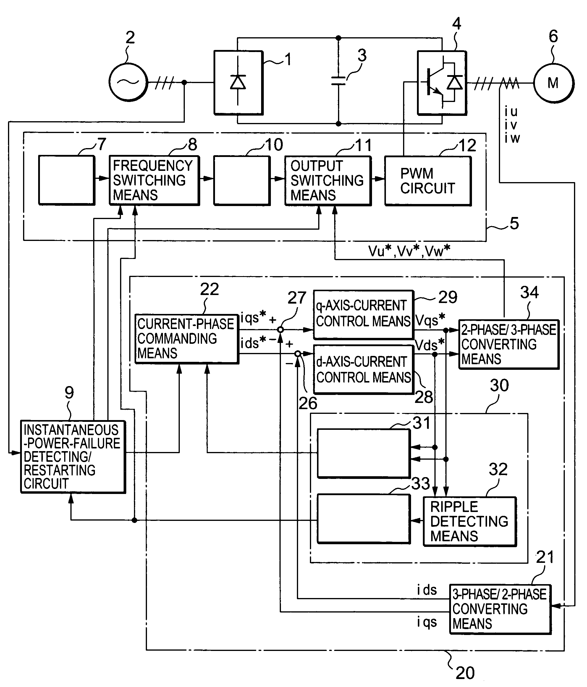
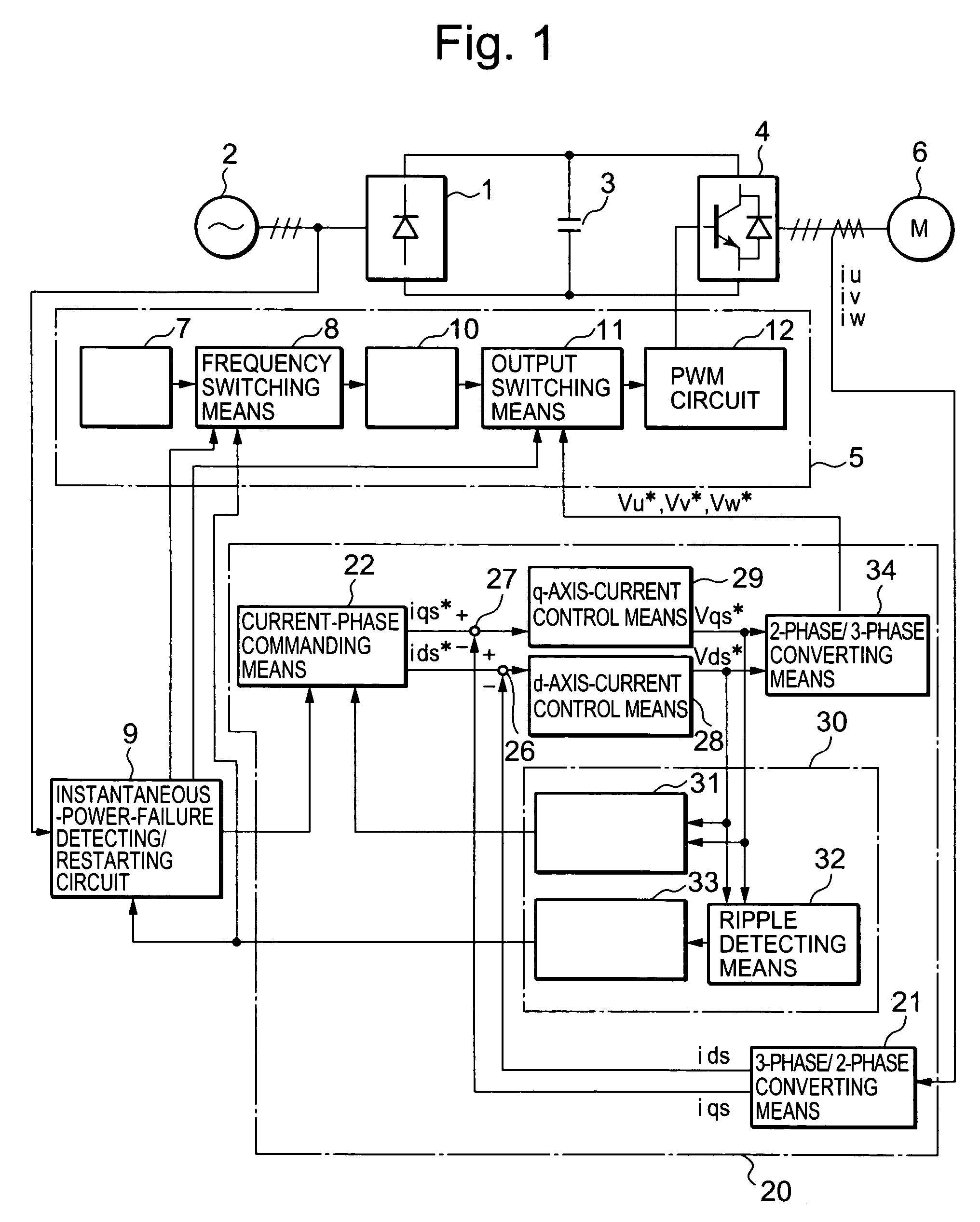
[0023]The configuration and the operation of an electric motor control system according to Embodiment 1 of the present invention will be discussed referring to FIG. 1. In FIG. 1, a rectifier circuit 1 converts 3-phase ac (alternating current) inputted from a 3-phase commercial power source 2 to dc (direct current), and the converted dc is smoothed by a main circuit capacitor 3. An inverter section 4 is constituted from a switching element such as a transistor, and a feedback diode connected in parallel with the switching element; control signals from control circuitry 5 on-off control the switching element so that dc power is inverted into variable-frequency and variable-voltage ac power; and thereby an induction motor 6 is variable-speed driven.

[0024]In cases where the induction motor 6 that has been in a standstill is restarted, an acceleration / deceleration commanding device 7 sets an output frequency f as rotating velocity of the induction motor, and then 3-phase commercial power...

embodiment 2

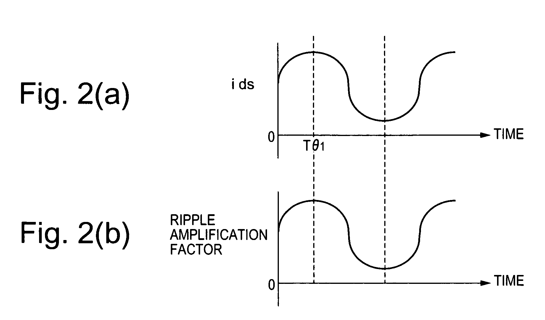
[0045]In FIG. 5, at (a) is a waveform of the d-axis component ids of the 2-phase current that the 3-phase / 2-phase converting means outputs; at (b) is a waveform of the integration term of the d-axis component vds* of the 2-phase-voltage command; and at (c) is a waveform of the q-axis component vqs* of the 2-phase-voltage command:

[0046]As represented in FIG. 5(b), when the phase is turned by 180 degrees at Tθ1 (the timing at which the integration term of vqs* has become below (V2+V3) / 2) while the residual voltage remains large, the center line of the waveform of the q-axis component vqs* of the 2-phase-voltage command becomes off the zero axis, as represented in FIG. 5(c), because the ripple becomes too large.

[0047]The rotating status (rotating frequency F and rotating direction) of a coasting induction motor is calculated based on the frequency fn of the ripple that superposes on the d-axis component vds* and the q-axis component vqs*, of the 2-phase-voltage command.

[0048]If “iqs*=0...


PUM


Abstract

In an electric motor control system according to the present invention, in restarting, after the effect of transient variation has been abated, a phase-reversal-timing detecting means 31 detects the first maximal value V1, the first minimal value V2, and the second maximal value V3, by comparing a value of the integration term of the d-axis component vds* of the 2-phase-voltage command outputted from the d-axis current control means 28 with its previous value, and then outputs a time at which the value of the integration term of the d-axis component vds* of the 2-phase-voltage command becomes below (the first minimal value V2+the second maximal value V3) / 2, as the first specific phase at which the current-commanding phase is turned by 180 degrees, to the current phase commanding means 22.

Description

TECHNICAL FIELD[0001]The present invention relates to electric motor control systems.BACKGROUND ART[0002]As a velocity controller for induction motors, constant-V / F-control-system inverters that control the ratio of output voltage V to output frequency F to be constant have been widely utilized. With regard to these inverters, when they are restarted, with electric power being restored, after they have been stopped due to the occurrence of instantaneous power failure, or when they are initiated under the circumstances that an induction motor is coasting on external force while the inverter is stopped, it is necessary to re-accelerate the coasting induction motor in such a manner that the rotating frequency F of the induction motor approximately coincides with the output frequency f of the inverter. Accordingly, when the constant-V / F-control-system inverters are initiated, it is necessary to learn the output frequency f of the inverter and the rotating frequency F of the coasting ind...

Claims


Application Information

Patent Timeline
Patent Type & Authority Patents(United States)
IPC IPC(8): H02P1/24H02P21/18H02P21/24H02P23/07H02P27/06H02P27/08
CPCH02P21/0035H02P21/22
Inventor EGUCHI, KIYOSHI
Owner MITSUBISHI ELECTRIC CORP
Why Eureka
Try Eureka