Battery ground fault detecting circuit

a fault detection circuit and battery technology, applied in emergency power supply arrangements, instruments, transportation and packaging, etc., can solve problems such as power failure, data loss of computer, and battery structure of uninterruptible power system

Active Publication Date: 2006-02-28
DELTA ELECTRONICS INC
View PDF7 Cites 9 Cited by
  • Summary
  • Abstract
  • Description
  • Claims
  • Application Information

AI Technical Summary

Problems solved by technology

Unstable power quality usually causes a damage, a crash or a data loss of the computer and all kinds of precision instruments, and thus, an uninterruptible power system gradually becomes an indispensable auxiliary equipment for the computer and all kinds of precision instruments.
Certainly, the main structure of the uninterruptible power system is the battery, whose power is saturated in peacetime.
However, because there is a possibility that the battery has a leakage that may cause a ground fault, or the terminal of the battery has a short fault to the ground owing to an inappropriate transportation or incorrect assembling, the battery might be damaged in a minor situation, or seriously, the battery might be burned, which causes a security problem or destroys the uninterruptible power system and thus results in the power failure.
Therefore, a spark and overheat might be occurred at the leakage, so that the case of the battery 121 might be overheated and burned.
Although the battery 121 can be positioned in a specially made insulation box for avoiding the leakage from contacting with the case, it is still undependable.
However, because the sensitivity of the ground leakage breaker 14 is still a problem, there is a possibility that an unusual or abnormal error might not be detected by this manner, and further, the cost thereof is higher.
However, because there exists impedance in the electrolyte when the leakage ground fault is occurred in the battery 121, this method still cannot detect the battery ground fault ranged in a middle magnitude owing to the precision problem.
However, because the capacity of this isolation transformer 18 has to be identical to that of the uninterruptible power system, the cost and installation space must be increased.
Therefore, in the viewpoint of cost-benefit, this detecting method is not a best processing way.
Certainly, the existence of undetectable fault will reduce the reliability of the uninterruptible power system.

Method used


Image

  • Battery ground fault detecting circuit
  • Battery ground fault detecting circuit
  • Battery ground fault detecting circuit

Examples


Embodiment Construction

[0029]The present invention will now be described more specifically with reference to the following embodiments. It is to be noted that the following descriptions of preferred embodiments of this invention are presented herein for purpose of illustration and description only; it is not intended to be exhaustive or to be limited to the precise form disclosed.

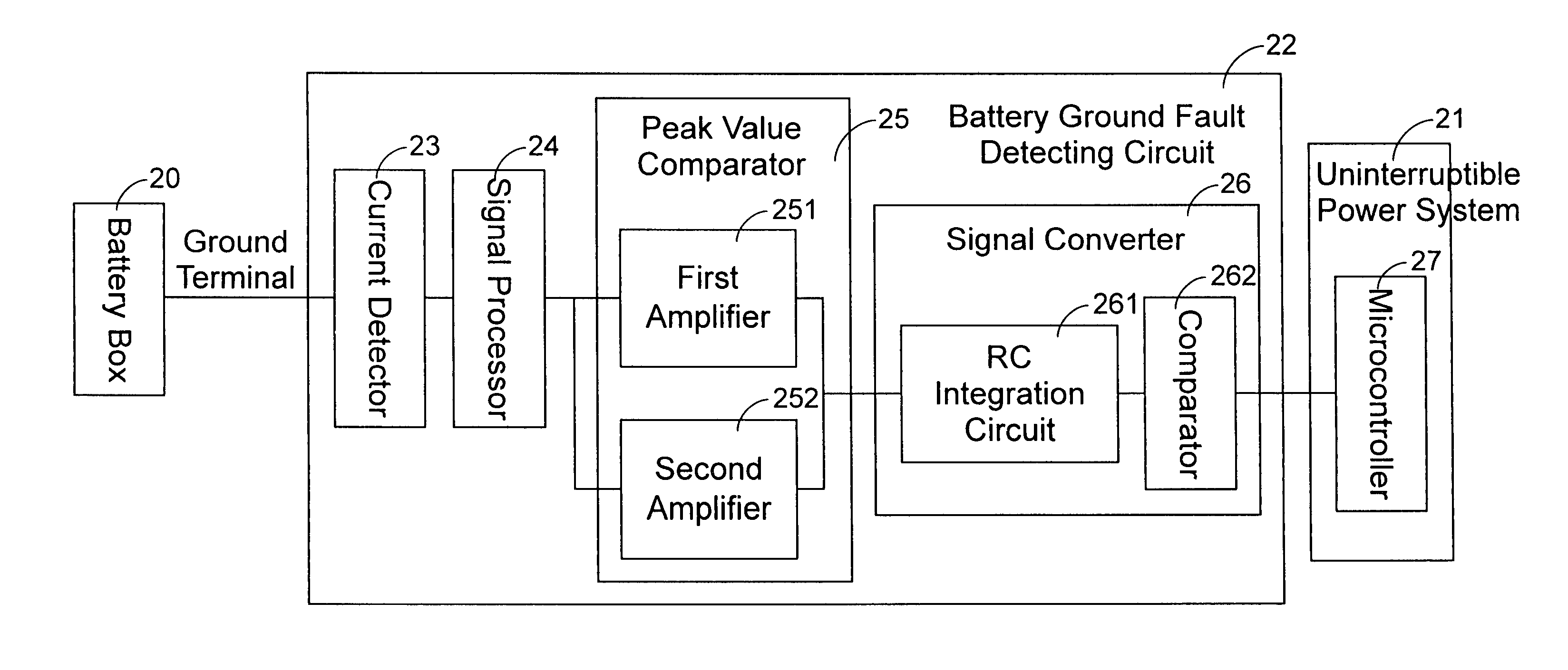
[0030]The present invention relates to a battery ground fault detecting circuit which is applied to an uninterruptible power system. The battery ground fault detecting circuit according to the present invention employs a current detector for detecting a ground current signal of a battery box, and a peak value comparator for comparison so as to decide whether the battery has a ground fault. And, the ground fault occurred in any battery box can be detected so that the unreliable, expensive or insensitive problems in the conventional battery ground fault detecting circuits can be solved.

[0031]Please refer to FIG. 2 which is a schema...


PUM

PropertyMeasurementUnit
ground currentaaaaaaaaaa
poweraaaaaaaaaa
voltageaaaaaaaaaa

Abstract

A battery ground fault detecting circuit applied to an uninterruptible power system is disclosed. The uninterruptible power system has a controller and is connected to a battery box having a ground terminal. The battery ground fault detecting circuit is employed for detecting whether a ground fault is occurred in a battery mounted in the battery box, so that the controller can execute a corresponding protection procedure. The battery ground fault detecting circuit includes a detector electrically connected to the ground terminal of the battery box for detecting a ground current signal outputted from the ground terminal, a signal processor electrically connected to the detector for filtering and amplifying the ground current signal, a peak value comparator electrically connected to the signal processor and having a predetermined peak value for comparing the filtered and amplified ground current signal with the predetermined peak value so as to generate an AC control signal when the peak value of the ground current signal is larger than the predetermined peak value, and a signal converter electrically connected to the peak value comparator for converting the AC control signal into a DC control signal and transmitting the DC control signal to the controller for executing a corresponding protection procedure to the uninterruptible power system in response to the DC control signal.

Description

FIELD OF THE INVENTION[0001]The present invention relates to a battery ground fault detecting circuit, and more particular to a battery ground fault detecting circuit applied to an uninterruptible power system.BACKGROUND OF THE INVENTION[0002]Unstable power quality usually causes a damage, a crash or a data loss of the computer and all kinds of precision instruments, and thus, an uninterruptible power system gradually becomes an indispensable auxiliary equipment for the computer and all kinds of precision instruments. The so-called uninterruptible power system, as implied by the name, is the equipment for supplying emergency power when the external power is cut off or abnormal, and it is generally box-shaped and composed of a battery, a monitor software and a relay. Certainly, the main structure of the uninterruptible power system is the battery, whose power is saturated in peacetime. Once the uninterruptible power system detects that the external power is disconnected or the voltag...

Claims


Application Information

Patent Timeline
Patent Type & Authority Patents(United States)
IPC IPC(8): G01R31/36G01N27/416G01R31/00G01R31/02
CPCG01R31/3606G01R31/025G01R31/382G01R31/52
Inventor LIAO, JEN-CHUANTSAI, WEN-CHE
Owner DELTA ELECTRONICS INC
Why Eureka
Try Eureka