Validation of the presence of an electromagnetic transponder in the field of an amplitude demodulation reader

a technology of amplitude demodulation and validation of the presence of an electromagnetic transponder, which is applied in the direction of transmission systems, visible signalling systems, indirect connection of subscribers, etc., can solve the problems of terminal undetected, terminal demodulator cannot detect the presence of data modulation, and transponder remote supplied by a terminal

Inactive Publication Date: 2006-02-28
STMICROELECTRONICS SRL
View PDF120 Cites 8 Cited by
  • Summary
  • Abstract
  • Description
  • Claims
  • Application Information

AI Technical Summary

Benefits of technology

[0020]The present invention aims at overcoming the disadvantages of conventional systems relative to the presence of demodulation gaps in the response of the demodulator of a read / write terminal.
[0021]More specifically, the present invention aims at providing a novel control method that makes a read / write terminal insensitive to demodulation gaps of the data that it receives from a transponder having entered its field.

Problems solved by technology

A problem that is posed in conventional electromagnetic transponder systems is that a transponder remotely supplied by a terminal and transmitting data to said terminal may be undetected by the terminal, that is, the terminal's demodulator cannot manage to detect the presence of a data modulation.
However, the terminal's demodulator does not detect this back-modulation.
As a result of this demodulation gap problem, a terminal cannot detect a transponder present in its field since this detection conventionally uses the result of the data demodulator on the terminal side.
An additional disadvantage is that, since the transponder has received data from the terminal, it believes that it is identified by the terminal, which is not true.
The only present techniques to isolate this phenomenon are to multiply the information exchanges to validate the transmission, which is costly in terms of transmission duration.
As a result of the extent of these manufacturing tolerances, perfect tuning is practically not respected and it cannot be guaranteed that a transponder entering the field of a terminal will not be, in a given coupling position, in a demodulation gap.
The combined problems of the existence of demodulation gaps and of the variation of the position of these demodulation gaps with respect to the distance between the inductances, associated with the manufacturing tolerances of the components, make conventional systems rather unreliable.

Method used


Image

  • Validation of the presence of an electromagnetic transponder in the field of an amplitude demodulation reader
  • Validation of the presence of an electromagnetic transponder in the field of an amplitude demodulation reader
  • Validation of the presence of an electromagnetic transponder in the field of an amplitude demodulation reader

Examples


Embodiment Construction

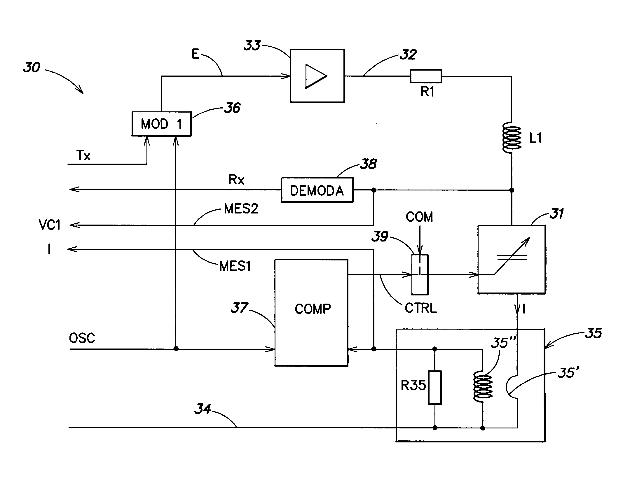
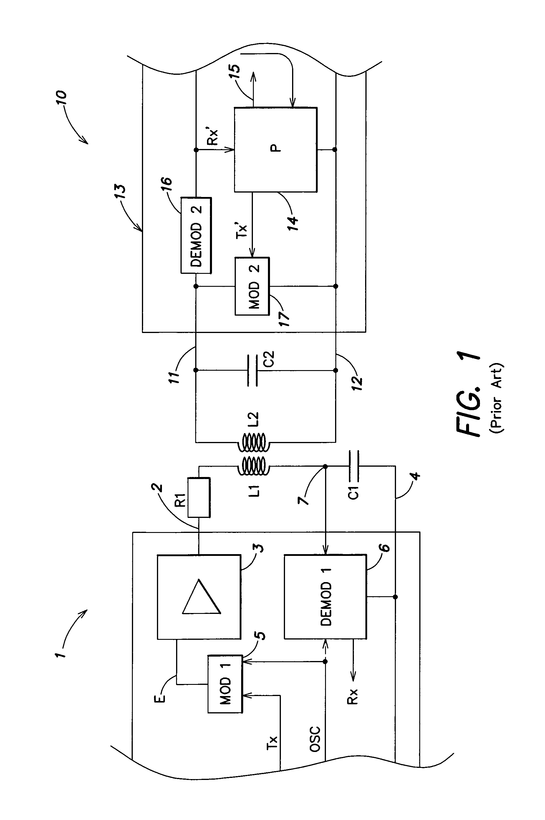
[0039]The same elements have been referred to with the same references in the different drawings. For clarity, only those elements of a terminal and of a transponder and only those steps of the information exchange process which are necessary to the understanding of the present invention have been illustrated in the drawings and will be described hereafter. In particular, the details constitutive of the modulators and demodulators have not been detailed and are within the abilities of those skilled in the art based on the functional indications given hereafter. Further, the present invention will be discussed in relation with transponders using a so-called “resistive” back-modulation to vary the load that they form on the terminal's oscillating circuit (the capacitances of the oscillating circuits of the transponders being fixed), but it should be noted that the present invention more generally applies to any type of back-modulation, for example to a so-called “capacitive” back-modu...


PUM


Abstract

A terminal for generating an electromagnetic field adapted to communicating with at least one transponder, and a method for controlling such a terminal including: an oscillating circuit adapted to being excited by a remote supply signal of the transponder; an amplitude demodulator for detecting possible data transmitted by the transponder; circuitry for regulating the signal phase in the terminal's oscillating circuit on a reference value; circuitry for measuring variables linked to the current in the oscillating circuit and to the voltage thereacross; and circuitry for comparing current values of these variables to predetermined values, to determine the presence of a transponder.

Description

BACKGROUND OF THE INVENTION[0001]1. Field of the Invention[0002]The present invention relates to systems using electromagnetic transponders, that is, transceivers (generally mobile) capable of being interrogated in a contactless and wireless manner by a unit (generally fixed), called a read and / or write terminal. Generally, transponders extract the power supply required by the electronic circuits included therein from the high frequency field radiated by an antenna of the read and write terminal.[0003]2. Discussion of the Related Art[0004]FIG. 1 very schematically shows a conventional example of a data exchange system of the type to which the present invention relates between a read / write terminal 1 and a transponder 10.[0005]Generally, terminal 1 is essentially formed of a series oscillating circuit formed of an inductance L1 in series with a capacitor C1 and a resistor R1, between an output terminal 2 of an amplifier or antenna coupler 3 and a terminal 4 at a reference potential (...

Claims


Application Information

Patent Timeline
Patent Type & Authority Patents(United States)
IPC IPC(8): H04Q5/22H04B1/59G06K7/00
CPCG06K7/0008
Inventor WUIDART, LUC
Owner STMICROELECTRONICS SRL
Why Eureka
Try Eureka