Communication control system and control method thereof

Inactive Publication Date: 2006-02-28
NEC CORP
View PDF15 Cites 9 Cited by
  • Summary
  • Abstract
  • Description
  • Claims
  • Application Information

AI Technical Summary

Benefits of technology

[0022]An object of the present invention is to eliminate the above-described shortcomings of conventional techniques and to provide a communication processing system which enables processing of sequential control, synchronous control, etc. conventionall

Problems solved by technology

As described in the foregoing, since in conventional sequential processing, a higher-order management layer confirms transfer at every packet transfer, a large overhead is generated such as consumption of CPU resources by polling and a delay caused by notification of an interruption and the subsequent confirmation thereof.
However, communication control systems operating these communication devices fail to fully make use of a capacity of high-speed media.
Main reason is overhead between a management layer realized by software and a data link layer realized by a communication device.
In a computer network, between a commu

Method used


Image

  • Communication control system and control method thereof
  • Communication control system and control method thereof
  • Communication control system and control method thereof

Examples


Example

[0130]A communication control system according to the first embodiment of the present invention adopts a system in which recording, in a descriptor of a logical channel of the side which first conducts transfer, the number of a waiting logical channel of the side which starts transfer next after the data transfer is completed enables a data link layer to execute sequential processing of data transfer based on the information. Hereinafter, the method is referred to as a passive system.

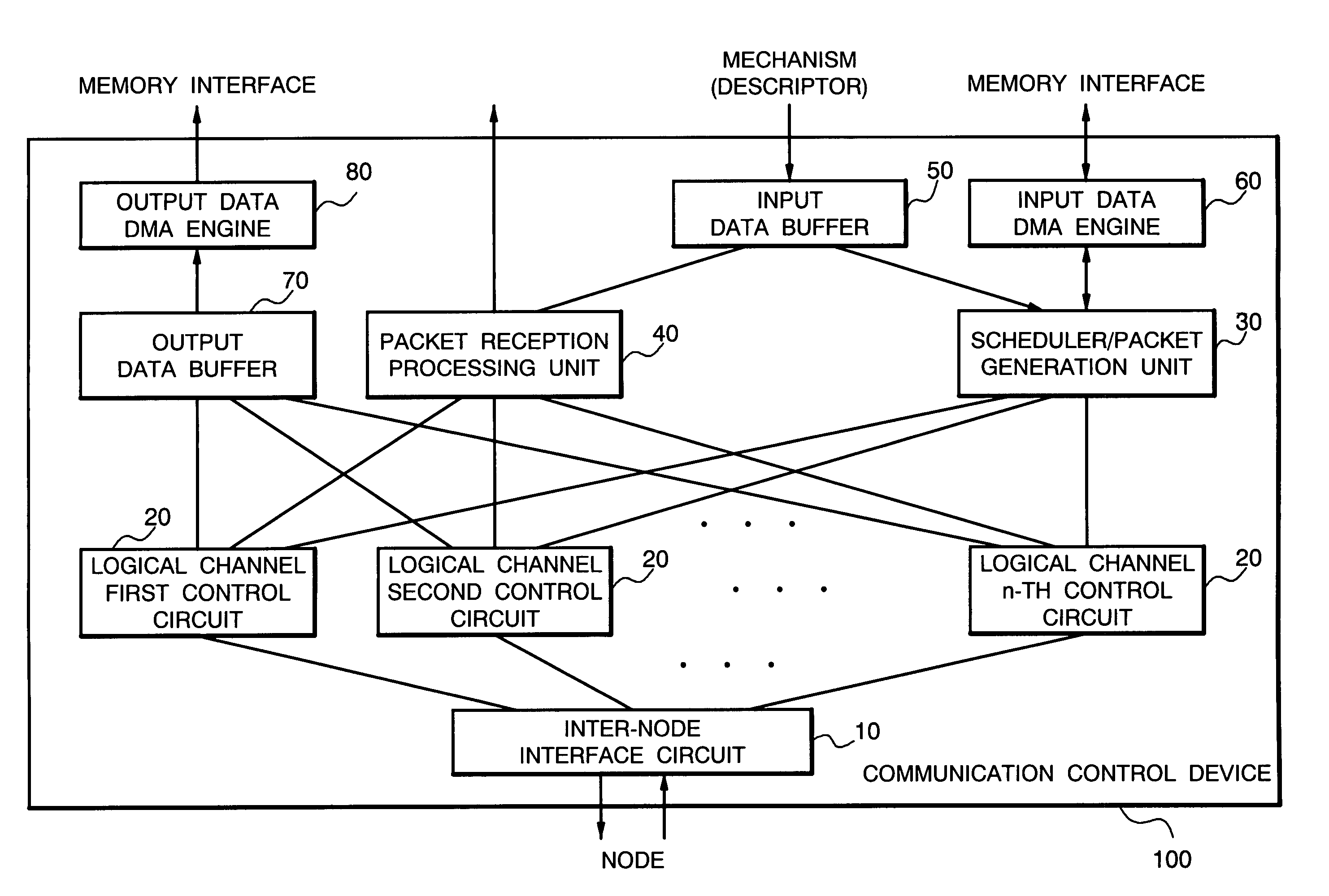
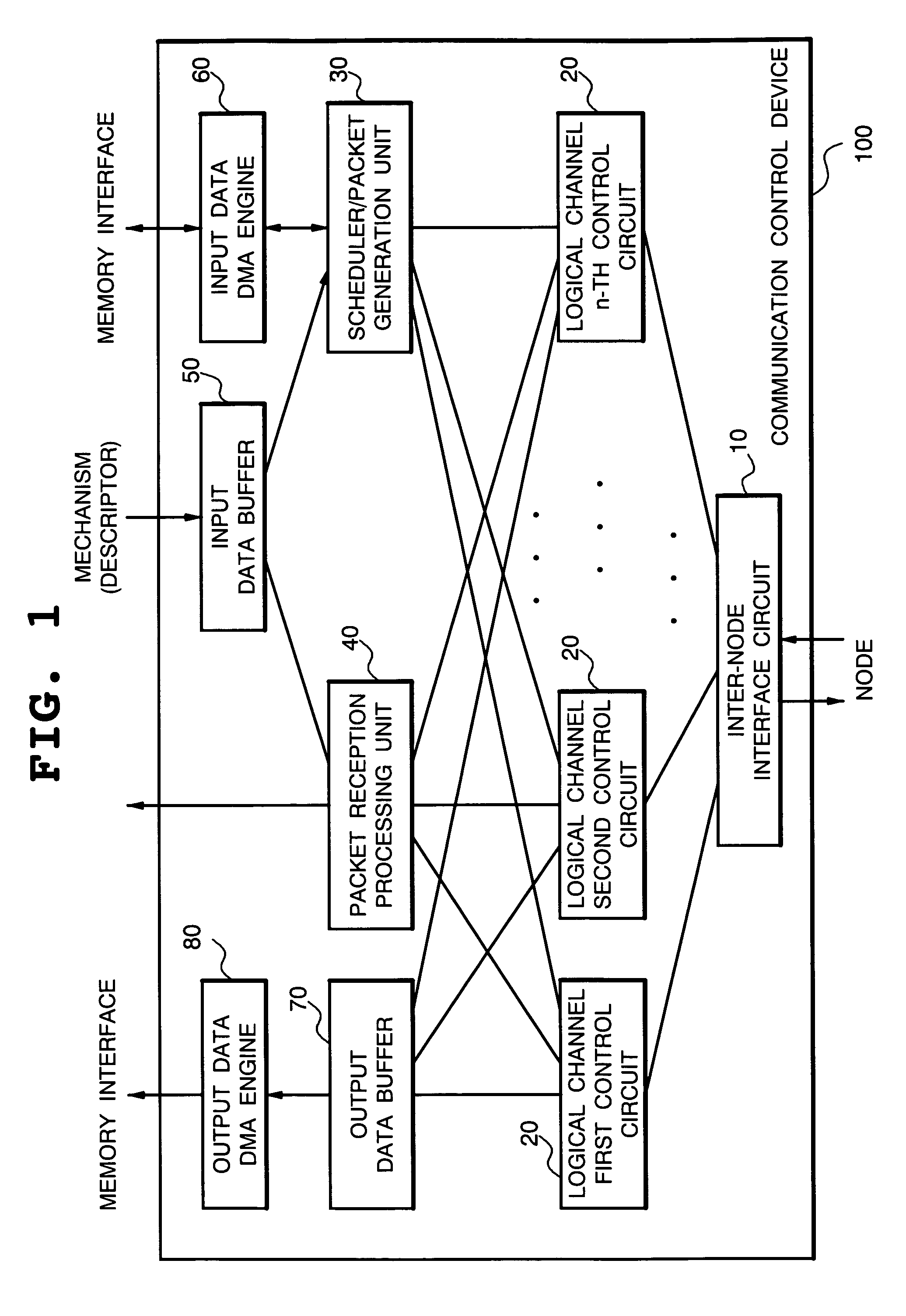
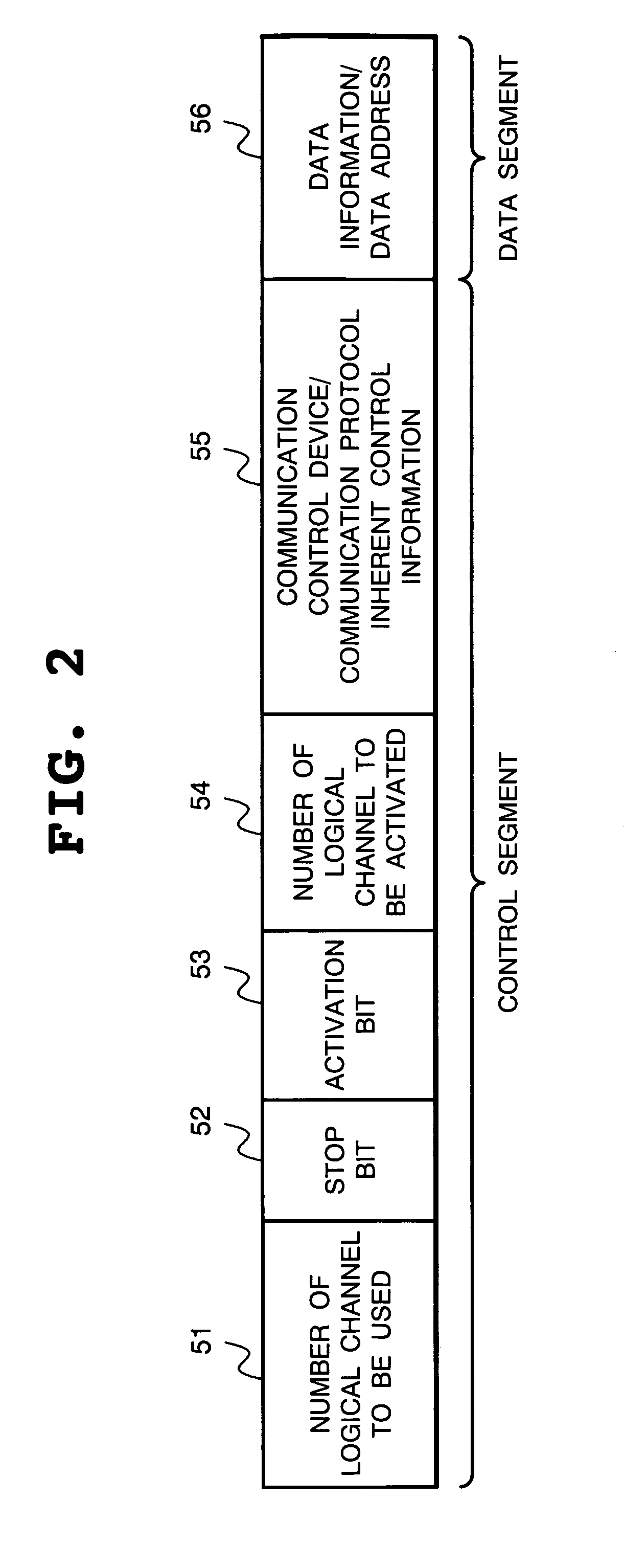
[0131]FIG. 1 is a block diagram showing a structure of a communication control system according to a first embodiment of the present invention and FIG. 2 is a diagram showing a format of a descriptor of the first embodiment of the present invention.

[0132]With reference to FIG. 2, the descriptor of the present embodiment includes a control segment in which control information of data transfer is described and a data segment in which information regarding data to be transferred is described.

[0133]The cont...

Example

[0166]Next, second embodiment of the present invention will be described.

[0167]A communication control system of the second embodiment of the present invention adopts a system in which in a descriptor of a logical channel of the side conducting transfer after temporary stop, the number of a logical channel of the side starting the preceding transfer whose transfer completion is a condition of the release of the temporary stop is recorded and a data link layer executes sequential processing of data transfer based on thus obtained information. Hereinafter, this system is referred to as an active system.

[0168]FIG. 5 is a block diagram showing a structure of the communication control system according to the second embodiment of the present invention, while FIG. 6 is a diagram showing a format of a descriptor according to the second embodiment of the present invention.

[0169]With reference to FIG. 6, similarly to the first embodiment, the descriptor of the present embodiment includes a co...


PUM


Abstract

In a communication control system for controlling packet transfer conducted by a plurality of logical channels between nodes, a circuit is provided for recording, in a descriptor for recording information regarding transfer by each logical channel, information including a stop bit, an activation bit, the number of logical channel to be activated, an identification value, the number of logical channel to be monitored and a monitoring identification value which are information regarding the order of transfer by each logical channel, and a data link layer includes a circuit for executing transfer by each logical channel based on the order of transfer by each logical channel designated by a descriptor.

Description

BACKGROUND OF THE INVENTION[0001]1. Field of the Invention[0002]The present invention relates to a communication control system for controlling packet transfer conducted by a plurality of logical channels and, more particularly, to a communication control system for conducting sequential processing and synchronous processing of transmission data at a high speed.[0003]2. Description of the Related Art[0004]In a communication control device for providing communication between nodes connected by a virtual channel protocol, at the time of conducting message transfer and data transfer between nodes by using packets, a logical channel is set up between the nodes by a management layer in charge of transfer control and, a descriptor which records information for transmission and reception is prepared for each packet transfer to activate a transmission and reception control circuit.[0005]Although the descriptor is analyzed by a data link layer of the communication control device, packet tran...

Claims


Application Information

Patent Timeline
IPC IPC(8): H04L12/56G06F13/00H04L29/08
CPCH04L49/901H04L49/90
Inventor ABE, SHINJIUENO, SHINJI
Owner NEC CORP
Why Eureka
Try Eureka