Gas turbine

a technology of gas turbine and combustion chamber, which is applied in the direction of machines/engines, mechanical equipment, lighting and heating apparatus, etc., can solve the problems of high thermal load on the components and parts exposed to said medium, the structure of the annular combustion chamber, and the chamber and the moving parts of the turbine unit, etc., to achieve fast and easy assembly, faster and better maintenance of the combustion chamber parts, and maintenance work can be carried out comparatively easily and quickly

Inactive Publication Date: 2006-03-07
SIEMENS AG
View PDF5 Cites 6 Cited by
  • Summary
  • Abstract
  • Description
  • Claims
  • Application Information

AI Technical Summary

Benefits of technology

[0010]The object of the invention is therefore to specify a gas turbine of the type mentioned above, wherein the inner wall of the combustion chamber can be dismantled comparatively quickly and easily.
[0018]The advantages achieved with the invention in particular comprise the fact that the parting joint screw connection of the combustion chamber walls allows comparatively easy and fast assembly of the combustion chamber walls. The possibility in particular of removing the inner wall of the combustion chamber allows faster and better maintenance of these combustion chamber parts. Time-consuming removal of the blades and vanes used in the further operation of the turbine unit is therefore not necessary as access is possible from the inside of the combustion chamber, so maintenance work can be carried out comparatively easily and quickly.

Problems solved by technology

With such high working medium temperatures however the components and parts exposed to said medium are exposed to high thermal loads.
The combustion chamber and the moving parts of the turbine unit in particular are however subject to increased wear and tear due to the thermal load and general attrition due to the throughflow of the working medium, with the result that gas turbines have to be regularly maintained so that damaged components can be replaced or repaired.
This annular combustion chamber structure however has some disadvantages, as the inner wall of the combustion chamber is not accessible for maintenance work.
Assembly work is therefore very labor- and time-intensive.
The comparatively long downtime of the gas turbine means that downtime costs are incurred in addition to gas turbine assembly costs, resulting in comparatively very high overall costs for maintenance and repair work on the gas turbine.

Method used


Image

  • Gas turbine
  • Gas turbine
  • Gas turbine

Examples


Embodiment Construction

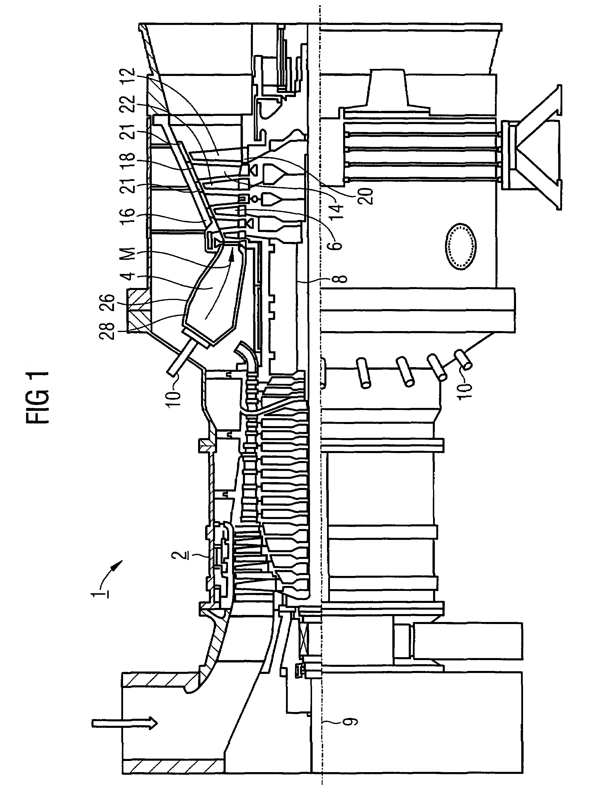
[0026]The gas turbine 1 according to FIG. 1 has a compressor 2 for combustion air, a combustion chamber 4 and a turbine 6 to drive the compressor 2 and a generator or machine (not shown). The turbine 6 and the compressor 2 are also arranged on a common turbine shaft 8 also referred to as the turbine rotor, to which the generator or machine is also connected, and which is positioned so that it can be rotated about its central axis 9. The combustion chamber 4 configured as an annular combustion chamber is fitted with a plurality of burners 10 to burn a liquid or gaseous fuel.

[0027]The turbine 6 has a plurality of rotatable blades 12 connected to the turbine shaft 8. The blades 12 are arranged in an overlapping ring shape on the turbine shaft 8, thereby forming a plurality of series of blades. The turbine 6 also has a plurality of fixed vanes 14 which are also attached in an overlapping ring shape on an inner housing 16 of the turbine 6 to form series of vanes. The blades 12 are hereby...


PUM


Abstract

In a gas turbine (1) with an annular combustion chamber (4), the combustion area (24) of which is bounded by an annular combustion chamber outer wall (26) on the one hand and by an annular combustion chamber inner wall (28) located therein on the other hand, it should be possible to dismantle the combustion chamber inner wall (28) comparatively quickly and easily. For this purpose according to the invention the combustion chamber inner wall (28) is formed by a plurality of wall elements attached to a support structure, wherein the support structure is formed by a plurality of sub-components abutting each other at a horizontal parting joint and the abutting sub-components (30) of the combustion chamber inner wall (28) are connected to each other at their horizontal parting joint by means of a plurality of screw connections (32) oriented at an angle to the inner wall surface.

Description

CROSS REFERENCE TO RELATED APPLICATIONS[0001]This application claims priority of the European application No. 02027495.7 EP, filed Dec. 10, 2002 under the European Patent Convention and which is incorporated by reference herein in its entirety.FIELD OF INVENTION[0002]The invention relates to a gas turbine with an annular combustion chamber, the combustion area of which is bounded by an annular outer wall on the one hand and an annular inner wall located therein on the other hand.BACKGROUND OF INVENTION[0003]Gas turbines are used in many fields to drive generators or machines. The energy content of a fuel is thereby used to generate a rotational movement of a turbine shaft. For this purpose the fuel is burned in a plurality of burners, with compressed air being supplied by an air compressor. Combustion of the fuel produces a high-temperature working medium at high pressure. This working medium is directed into a turbine unit connected downstream from the respective burner, where it e...

Claims


Application Information

Patent Timeline
Patent Type & Authority Patents(United States)
IPC IPC(8): F23R3/60F23R3/42F23R3/00F23R3/46F23R3/50
CPCF23R3/005F23R3/60F23R3/50
Inventor SCHULTEN, WILHELM
Owner SIEMENS AG
Why Eureka
Try Eureka