Handcuffs

a technology of handcuffs and handcuffs, which is applied in the direction of handcuffs, building locks, constructions, etc., can solve the problems that the handcuff, or the handcuff, defeats the purpose of the handcu

Inactive Publication Date: 2006-03-07
FTD LLC
View PDF53 Cites 9 Cited by
  • Summary
  • Abstract
  • Description
  • Claims
  • Application Information

AI Technical Summary

Benefits of technology

[0090]In the locked position, rotation of cam 5 in cavity 31 is prevented by detent ball 18 in detent 59; rotation of swing arm 9 in any direction is prevented because gear 7 cannot rotate in any direction. In this regard, when swing arm 9 is urged to rotate in the closing direction which, in consequence, urges gear 7 to rotate in the closing direction, linear force thus generated by contact between teeth 79 of gear 7 and the slanted side of end 55 cannot cause pin 52 to compress biasing

Problems solved by technology

It is apparent that a handcuff, or handcuffs, which can be opened and removed by the person being restrain

Method used


Image

  • Handcuffs
  • Handcuffs
  • Handcuffs

Examples


Embodiment Construction

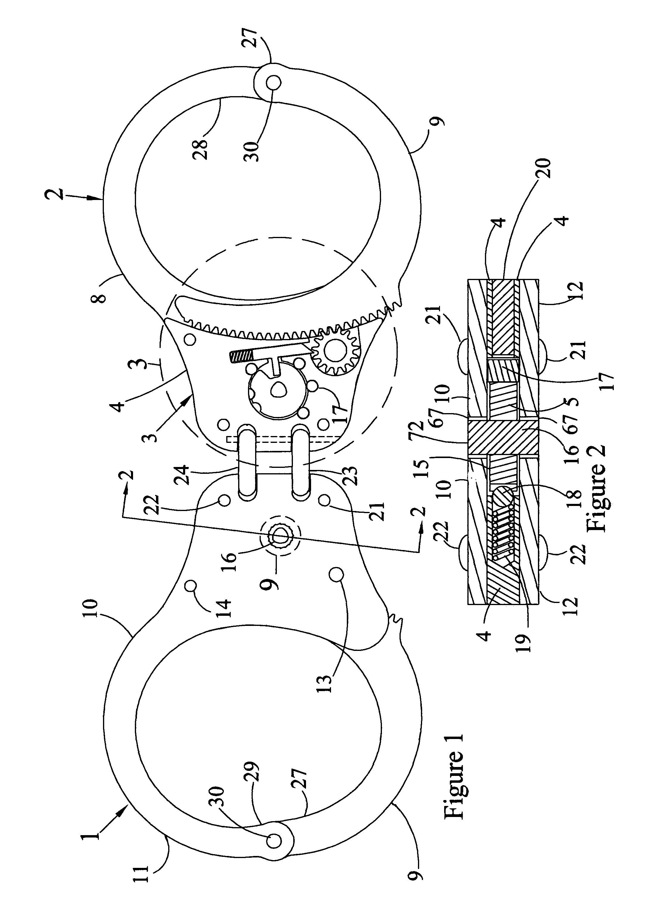
[0054]Referring now to FIGS. 1, 2 and 3, a set of handcuffs is shown consisting of left handcuff 1 and right handcuff 2. Handcuff 1 and handcuff 2 are identical, accordingly, unless specifically stated to the contrary, a reference numeral made with reference to one of the two handcuffs applies to the other.

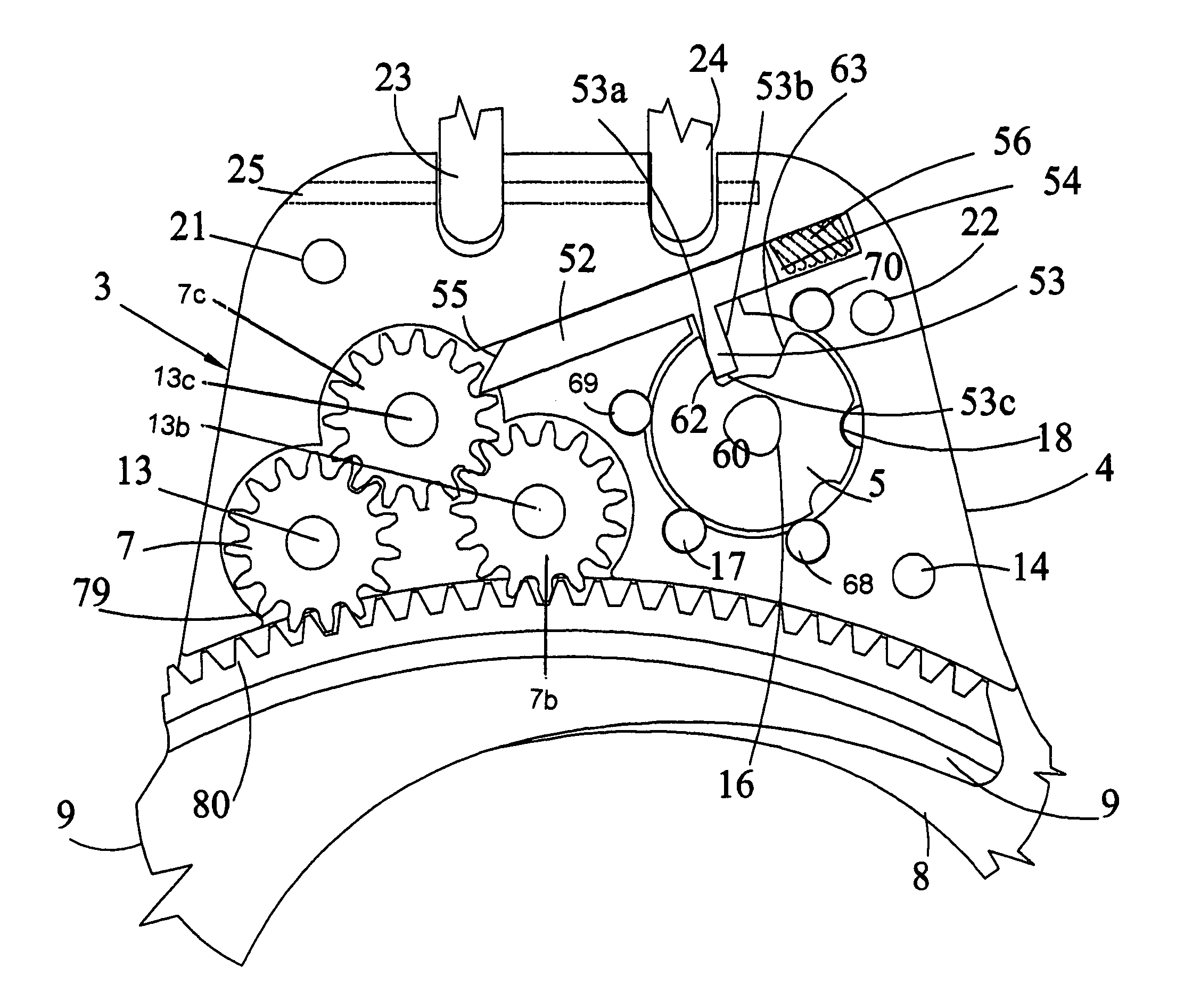
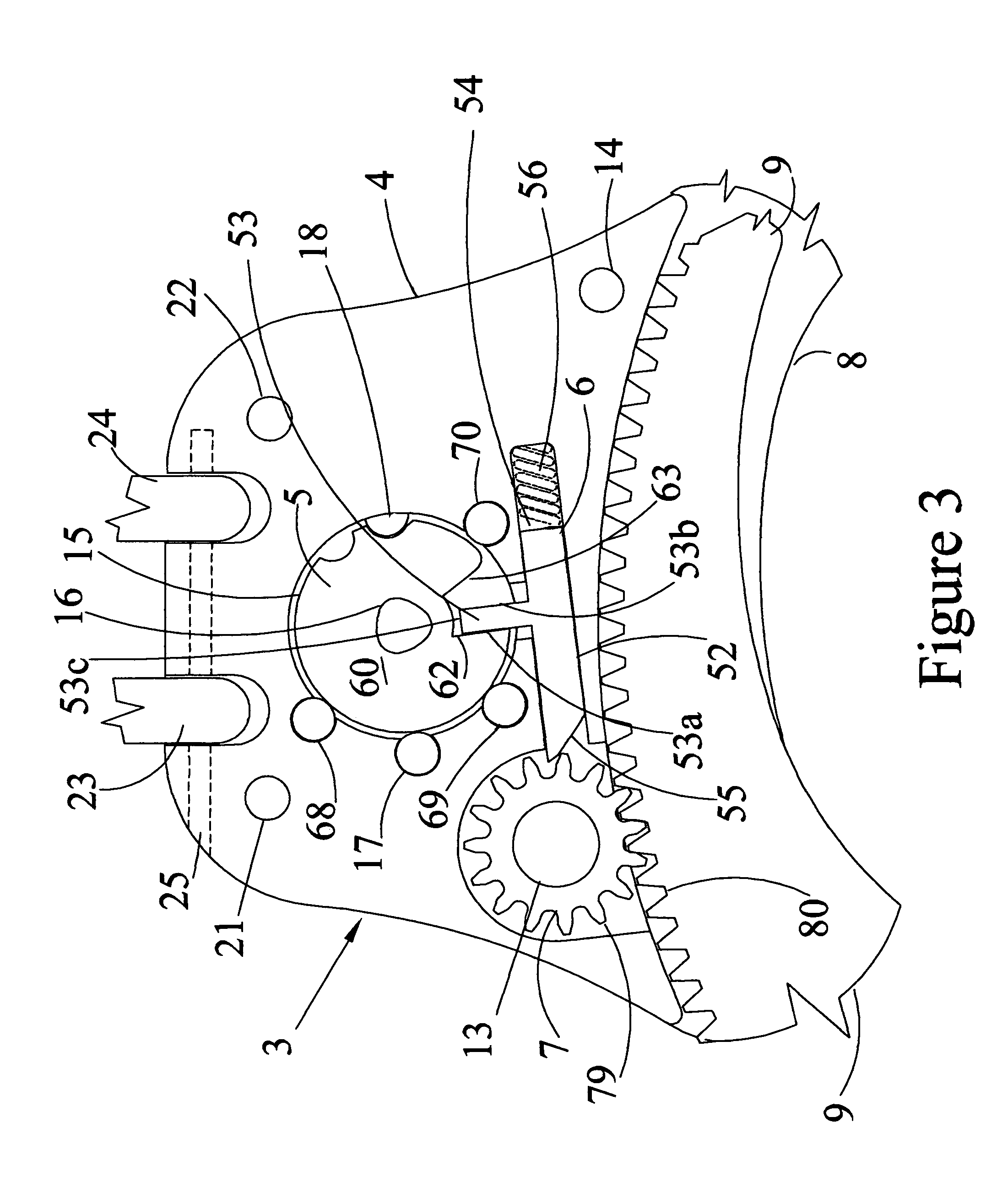
[0055]Top cheek plate 10 and plate arm 11 of right handcuff 2 are not shown in order to reveal machinery space 3 consisting of machinery housing 4 which contains rod cam 5, control rod 6 and working gear 7. The view of right handcuff 2 also shows the inside surface of plate arm 8 and swing arm 9.

[0056]The view of the left handcuff 1 shows the outside surface of top cheek plate 10, plate arm 11 and a partial view of swing arm 9. FIG. 2, a section view of left handcuff 1, shows top cheek plate 10, bottom cheek plate 12, machinery housing 4, gear axle 13, rivets 21 and 22 and rod cam 5 consisting of cam plate 15 and cam shaft 16. FIG. 2 also shows dowel 17, detent ball 18, detent spr...


PUM


Abstract

An apparatus for controlling the rotation of a gear comprising rotating a cam which causes the linear movement of a rod to control the rotation of the gear, wherein the cam rotates within a confined space but not around a fixed axle. The apparatus is particularly useful for controlling the opening and closing movements of a handcuff whose operating elements are comprised of a swing arm and at least one gear having teeth which engage the teeth of the swing arm.

Description

[0001]This is a continuation-in-part of U.S. application Ser. No. 10 / 1766,235 filed Jan. 28, 2004, now U.S. Pat. No. 6,978,644, which is a continuation-in-part of application Ser. No. 10 / 394,668, filed Mar. 21, 2003, now U.S. Pat. No. 6,684,666 issued Feb. 3, 2004, which is a continuation-in-part of application Ser. No. 10 / 091,272, filed Mar. 5, 2002, now U.S. Pat. No. 6,568,224 issued May 27, 2003.BACKGROUND OF THE INVENTION[0002]1. Technical Field of the Invention.[0003]This invention broadly relates to locking devices. The invention further relates to locking devices useful to physically restrain the movement by an individual of his or her arms and / or legs. This invention more particularly relates to mechanical restraining devices referred to in the art as “handcuffs.” This invention specifically relates to an operating and a locking mechanism for a handcuff.[0004]2. Description of the Prior Art and Problems Solved.[0005]It is known in the art that a handcuff is an apparatus whic...

Claims


Application Information

Patent Timeline
IPC IPC(8): E05B75/00
CPCE05B75/00Y10T70/404
Inventor TAPER, WILLIAM D.
Owner FTD LLC
Why Eureka
Try Eureka