
Multi-hit transparent armor system

a transparent armor and multi-hit technology, applied in the direction of doors/windows, bank protection devices, shutters/movable grilles, etc., can solve the problems of high risk of subsequent impacts, high cost, and high cost of materials brittleness or limited ability to withstand multiple impacts, etc., to achieve efficient and effective

Inactive Publication Date: 2006-03-07
ARMY UNITED STATES GOVERNMENT AS REPRESENTED BY THE SEC OF THE
View PDF7 Cites 11 Cited by
  • Summary
  • Abstract
  • Description
  • Claims
  • Application Information

AI Technical Summary

Benefits of technology

The solution effectively enhances the resistance of transparent armor systems to multiple impacts by rapidly deploying an opaque panel, ensuring continued protection and allowing for assessment of threats through visibility features, thereby improving security against multiple hits.

Problems solved by technology

The principal problem with transparent armors is that they generally incorporate glass or ceramic materials as major construction materials.
These materials are either very brittle or have limited ability to withstand multiple impacts or hits from small arms projectiles.
The initial impact on such materials often causes wide spread damage over a large surface area, and leaves them highly vulnerable to subsequent impacts.
Thereby, an assailant may defeat a transparent armor system merely by firing into it until the accumulative damage renders the armor system ineffective.
Because most modern infantry rifles have magazine capacities approaching 30 rounds, or more, this is a serious problem with sufficient risk to defeat most transparent armor systems.
When a first projectile is fired at the window by an assailant, the tempered glass will be subjected to loss of structural integrity or global failure upon impact.

Method used


Image

  • Multi-hit transparent armor system
  • Multi-hit transparent armor system

Examples


Embodiment Construction

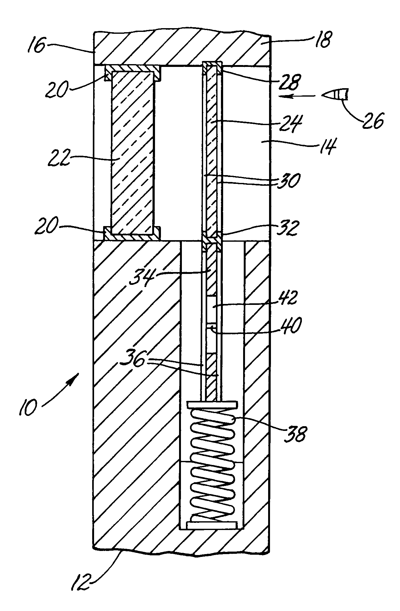
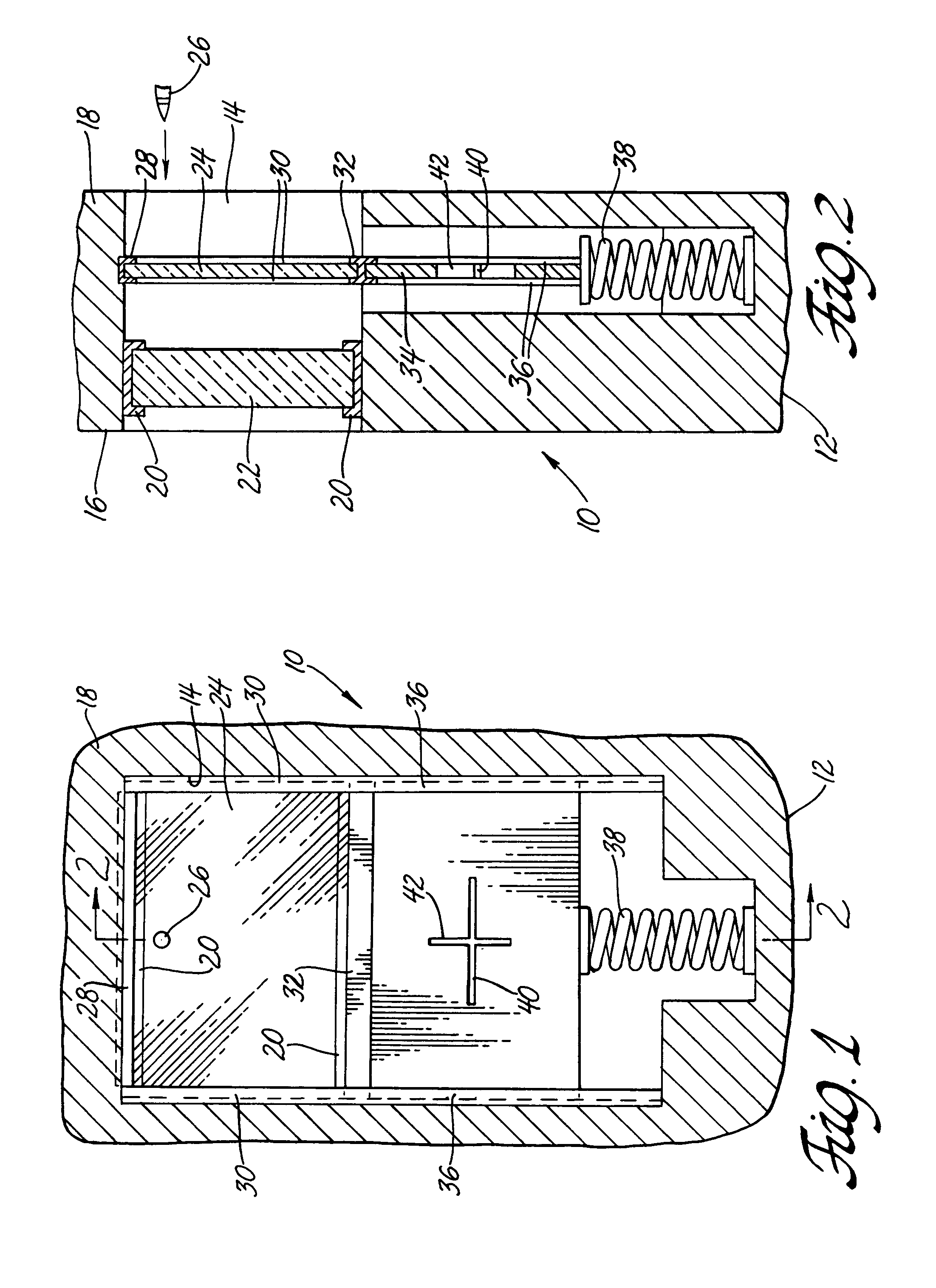
[0010]According to my invention, and referring to FIGS. 1 and 2, there is shown therein my window armor system 10 which has been installed within a security vehicle (not fully shown). FIG. 2 to is a sectioned, side view of FIG. 1 taken along line A—A. While the right-side wall 12 of a security vehicle is depicted in FIG. 2, it should be apparent that the left-side wall (not depicted) will be an exact mirror image of FIG. 2. Moreover, it should be appreciated that wall 12 could also be part of a building, or like structure, that provides ballistic protection for occupants.

[0011]A windowed opening 14 within wall 12 completely extends from an inboard or inner side 16 of said wall to an outboard or exposed side 18. Positioned within opening 14 near the inner side 16 are channeled frame(s) 20 that hold a transparent armor plate 22. While this plate is shown herein as a unitary, homogenous structure, it will be appreciated by those skilled in the art that this plate can be formed of multi...


PUM


Abstract

A multi-hit transparent armor system is described and claimed herein for improving the resistance of transparent armor to incoming projectiles. Typically, the transparent armor is framed within a window opening of a security structure. An exemplary, contemplated structure is an armored combat vehicle. My system includes a sheet of tempered glass that is also positioned within said window, but is deployed outboard of said transparent armor and is also parallel planar thereto. Positioned below said sheet of tempered glass, and coaxial thereto, is an opaque armor panel that is more efficient and effective against multiple projectiles than either the tempered glass or transparent armor alone. The tempered glass sheet and the opaque armor are typically loaded under compression by a spring assembly. An incoming projectile, launched from a position outboard and also remote from said structure, will first strike the tempered glass before hitting my transparent armor. Thereby, the tempered glass sheet will undergo global failure and is effectively removed from the window opening. In turn, the spring assembly translates the opaque armor into the position formerly occupied by the tempered glass sheet. Subsequently arriving projectiles are then defeated by the opaque armor panel.

Description

GOVERNMENT INTEREST[0001]The invention described herein may be made, used, and licensed by, or for, the United States Government for governmental purposes without paying me any royalty.BACKGROUND AND SUMMARY[0002]This invention pertains to transparent armor systems that are subject to multiple hits by small arms fire or other projectiles. In particular, my invention provides an improved armor system for windows of structures and security vehicles that may come under potential attack by terrorists or assailants.[0003]In the general field of ballistic armors, it is widely accepted that transparent armor plate (bullet-resistant glasses) will be used for windows of security vehicles and structures. These glasses are well known in the art and are commercially available from a variety of worldwide vendors.[0004]The principal problem with transparent armors is that they generally incorporate glass or ceramic materials as major construction materials. These materials are either very brittle...

Claims


Application Information

Patent Timeline
Patent Type & Authority Patents(United States)
IPC IPC(8): F41H5/013
CPCF41H5/013F41H5/263F41H5/24F41H5/0407
Inventor GONZALEZ, RENE' G.
Owner ARMY UNITED STATES GOVERNMENT AS REPRESENTED BY THE SEC OF THE
Learn More