Loading platform with twin roller conveyors

a technology of roller conveyors and loading platforms, which is applied in the direction of conveyor parts, loading/unloading, transportation and packaging, etc., can solve the problems of dangerous standing on the roller conveyor, awkward positioning, and ineffective force application for moving merchandis

Inactive Publication Date: 2006-03-07
BRANNON JAMES D
View PDF24 Cites 78 Cited by
  • Summary
  • Abstract
  • Description
  • Claims
  • Application Information

AI Technical Summary

Benefits of technology

[0003]The improved loading platform uses two parallel roller conveyors with a walkway there between. This permits the workman to place at least one foot on the walkway separating the conveyors when pushing a container or appliance off the loading platform or when placing such item onto the loading platform. Thus the workman can apply effective cargo moving force from a correct force applying position. This attachment reduces worker fatigue and injury potential and also increases efficiency through reduction of time required to load and unload merchandise. The improved loading platform places the sockets for the legs of an upright brace in a side support beam for one of the roller conveyors so as to not obstruct the walkway between the roller conveyors.

Problems solved by technology

When moving large boxes or crates onto or off of the roller conveyor, the workman must stand at one side of or at the end of the roller conveyor and these positions are awkward and not the most effective for applying force to move the merchandise on to or off of the roller conveyor.
Since the roller braking mechanism is released during loading and unloading, it would be dangerous to stand on the roller conveyor during loading or unloading operations in attempting to gain a force applying advantage relative to the conveyed merchandise.

Method used


Image

  • Loading platform with twin roller conveyors
  • Loading platform with twin roller conveyors
  • Loading platform with twin roller conveyors

Examples


Embodiment Construction

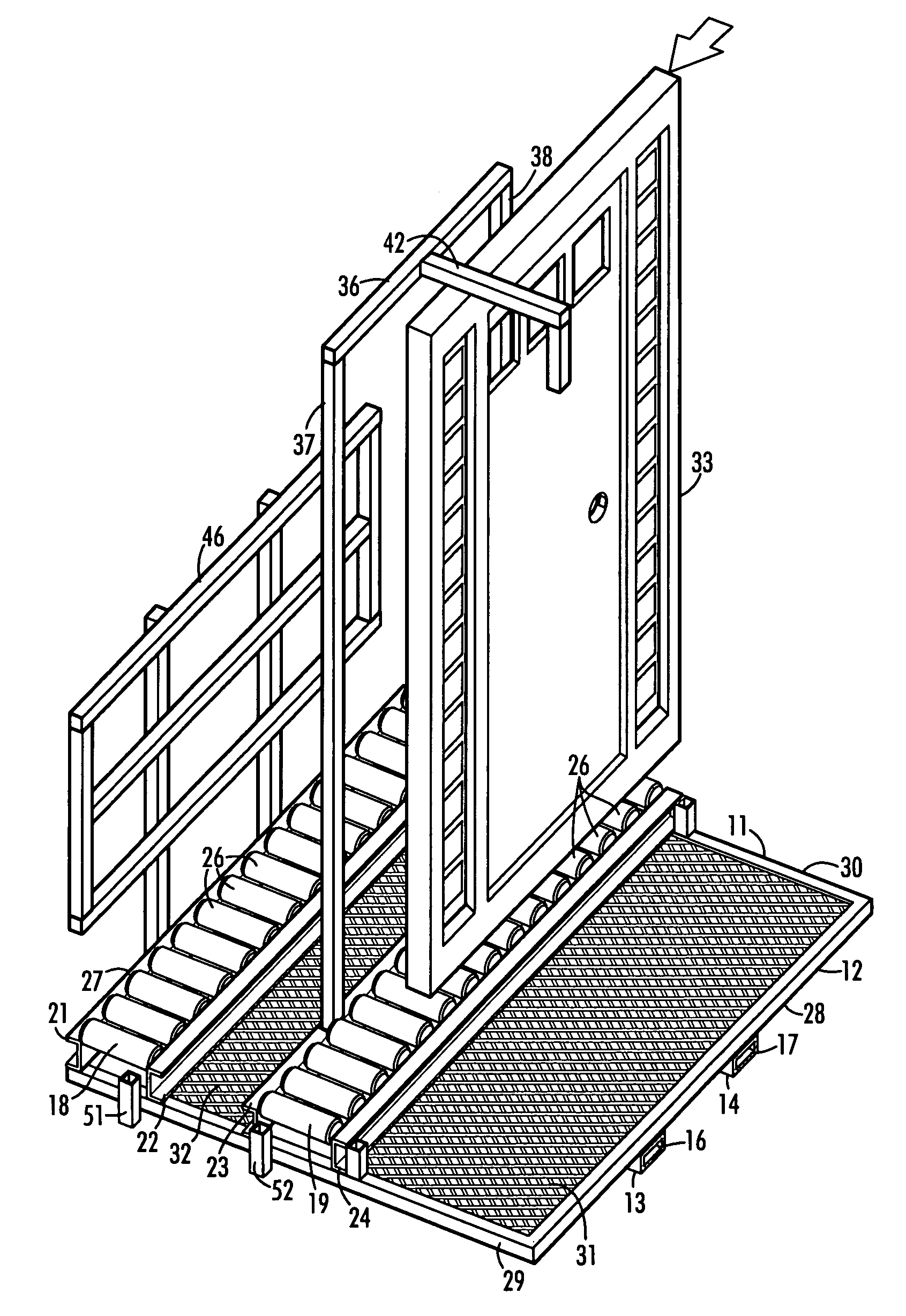
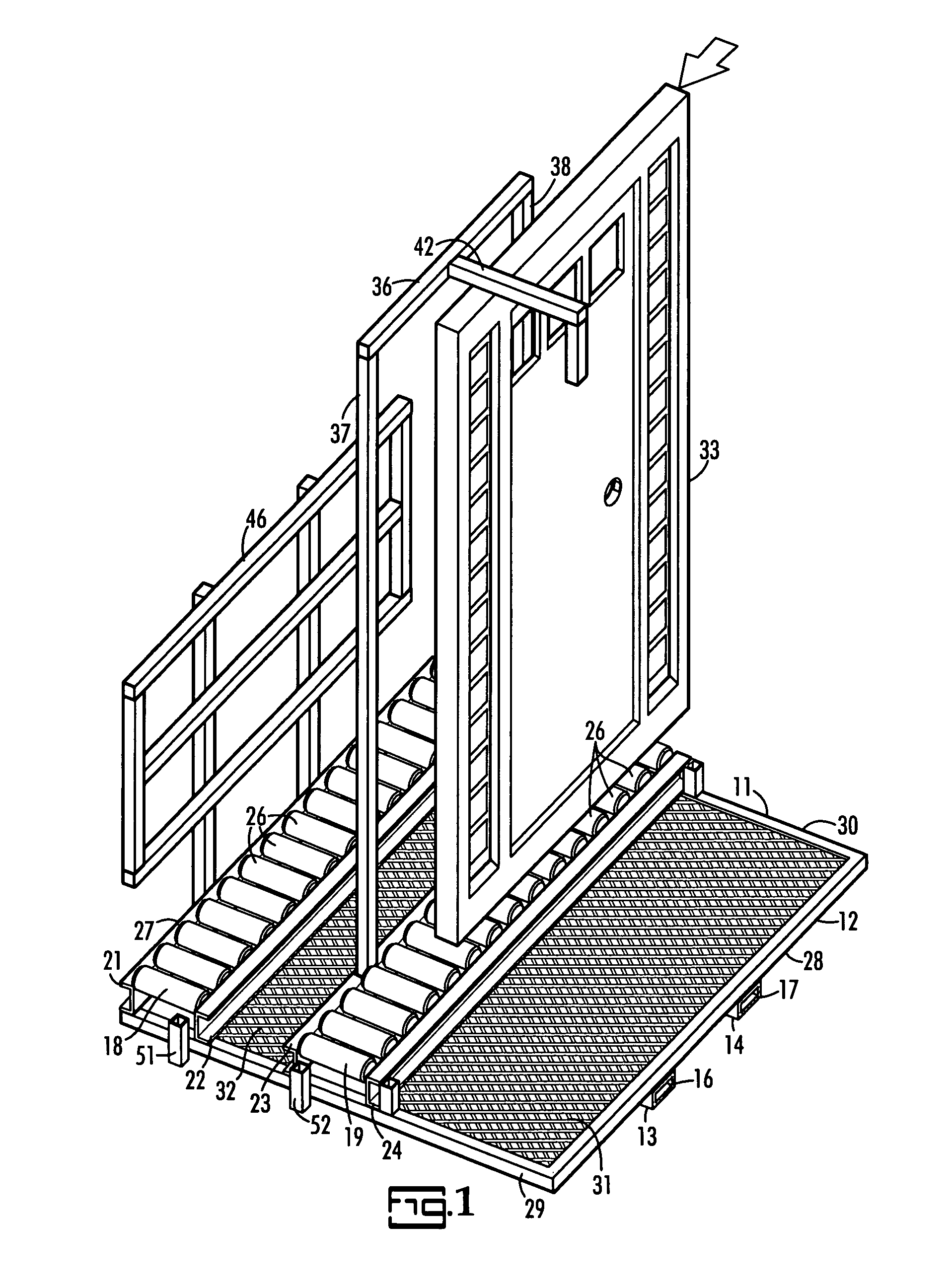
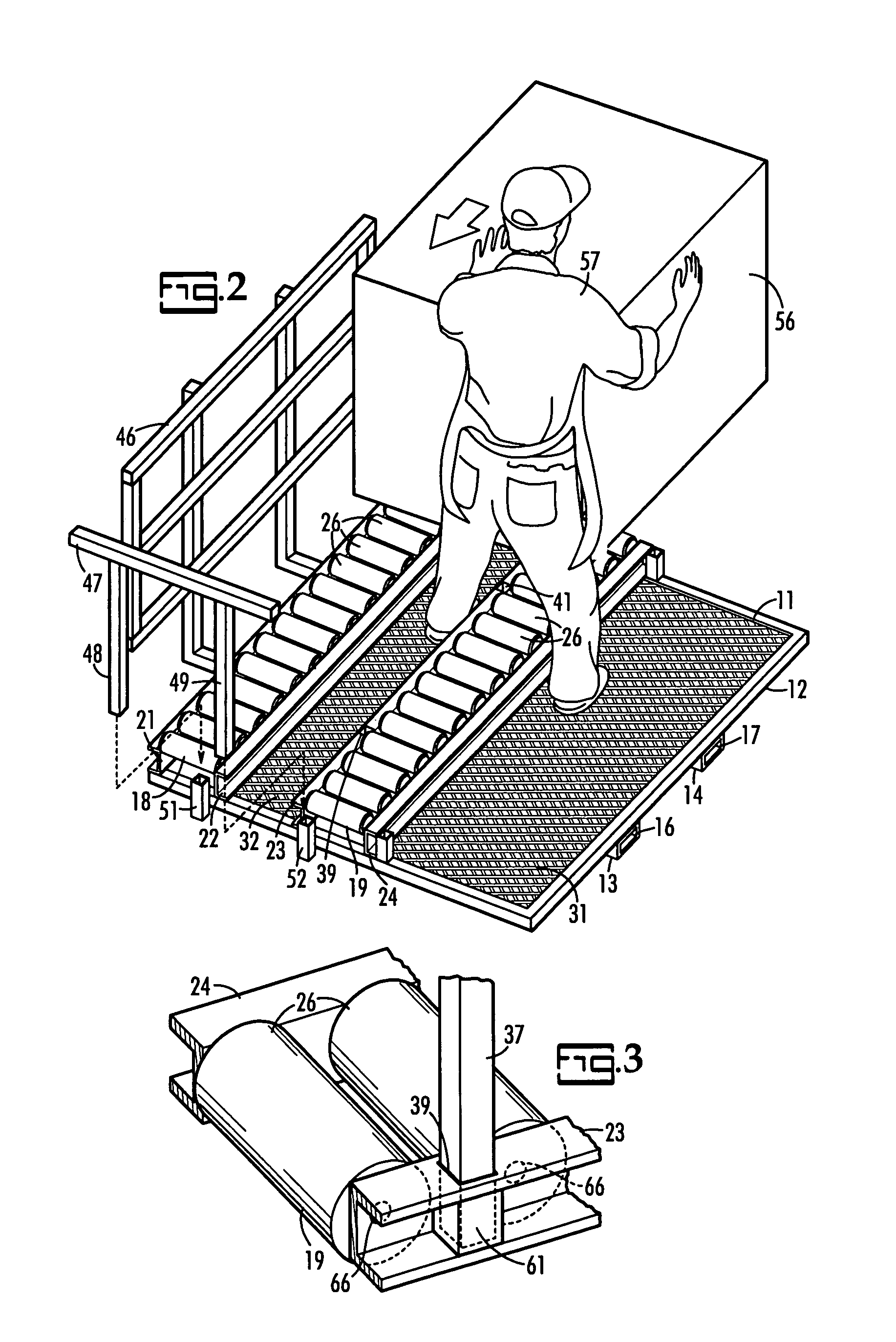
[0008]FIG. 1 illustrates a lift truck attachment in the form of a load transfer platform 11 which includes a horizontally disposed deck 12 having a pair of parallel laterally spaced hollow frame members 13, 14 extending front to rear on its underside and presenting end openings 16, 17 adapted to receive a pair of laterally spaced forks of an order picker lift truck, not shown, or other material handling vehicle. A pair of parallel horizontal and roller conveyors 18, 19, spaced from one another in a front to rear direction of the attachment are mounted on the top side of the deck 12 by parallel roller support beams 21, 22, 23, 24 which rotatably support the shafts 66 of the cylindrical rollers 26, as shown in FIG. 3. The deck 12 has a front side 27, a rear side 28 and a laterally opposite sides 29, 30. The deck 12 includes a floor segment 31 at the backside of the roller conveyor 19 and a floor segment 32 between the roller conveyors 18, 19. The fore and aft extending hollow frame me...


PUM


Abstract

A load transfer platform adapted for attachment to a lift has a pair of laterally extending roller conveyor which are space in a front to rear direction thereby providing a pathway there between for a workman loading and unloading merchandise.

Description

RELATED APPLICATIONS[0001]This invention is an improvement of the loading platform disclosed in the inventor's U.S. patent application Ser. No. 10 / 607,700 filed Jun. 27, 2003 for a Loading Platform Assembly for which benefit under 35 U.S.C. 120 is claimed.BACKGROUND OF THE INVENTION[0002]Warehouse type home improvement and builders supply stores use order picker lift trucks to move bulky merchandise between storage, point of display and customer loading. The hereinbefore identified loading platform assembly is a lift truck attachment designed to quickly and safely provide transport for wide entryway or patio door modules and large crates or appliances. When moving large boxes or crates onto or off of the roller conveyor, the workman must stand at one side of or at the end of the roller conveyor and these positions are awkward and not the most effective for applying force to move the merchandise on to or off of the roller conveyor. Since the roller braking mechanism is released durin...

Claims


Application Information

Patent Timeline
Patent Type & Authority Patents(United States)
IPC IPC(8): B65G47/00B65G69/22
CPCB65G69/22
Inventor BRANNON, JAMES D.
Owner BRANNON JAMES D
Why Eureka
Try Eureka