High energy containment device and turbine with same

a containment device and high energy technology, applied in the direction of mechanical control devices, process and machine control, instruments, etc., can solve the problems of increasing the likelihood of piercing or otherwise damaging a housing or containment vessel, adding weight and cost to the device, and kinetic energy of fragments released during failure, so as to reduce the likelihood of piercing and high kinetic energy

Inactive Publication Date: 2006-03-07
THE BOEING CO
View PDF26 Cites 23 Cited by
  • Summary
  • Abstract
  • Description
  • Claims
  • Application Information

AI Technical Summary

Benefits of technology

[0012]Thus, the containment device of the present invention can contain debris released by or into a rotary device, including such materials having high kinetic energy. In addition, the containment device reduces the likelihood of piercing or other damage that results from debris that defines sharp edges or points.

Problems solved by technology

Due to the high speed and / or mass of conventional rotary devices, the fragments released during failure can have significant kinetic energy.
Therefore, the housing must be strong in order to contain the fragments, typically requiring a thick housing that adds weight and cost to the device.
An increased likelihood of piercing or otherwise damaging a housing or containment vessel exists where the rotary device has sharp edges extending radially outward.
However, even where the rotary device does not have sharp outer edges, sharp edges can be formed if the rotary device fails.
For example, typical flywheels that are used for energy storage often fail by breaking into three segments.
Thus, only limited rotation of the segments can occur before the segments collide with the housing, thereby limiting the possibility that the broken edges of the segments will contact the housing.
On the other hand, if the housing or other containment vessel is located some significant distance from the flywheel or other high energy rotary device, piercing and other damage is more likely to occur.

Method used


Image

  • High energy containment device and turbine with same
  • High energy containment device and turbine with same
  • High energy containment device and turbine with same

Examples


Embodiment Construction

[0018]The present invention now will be described more fully hereinafter with reference to the accompanying drawings, in which some, but not all embodiments of the invention are shown. Indeed, this invention may be embodied in many different forms and should not be construed as limited to the embodiments set forth herein; rather, these embodiments are provided so that this disclosure will satisfy applicable legal requirements. Like numbers refer to like elements throughout.

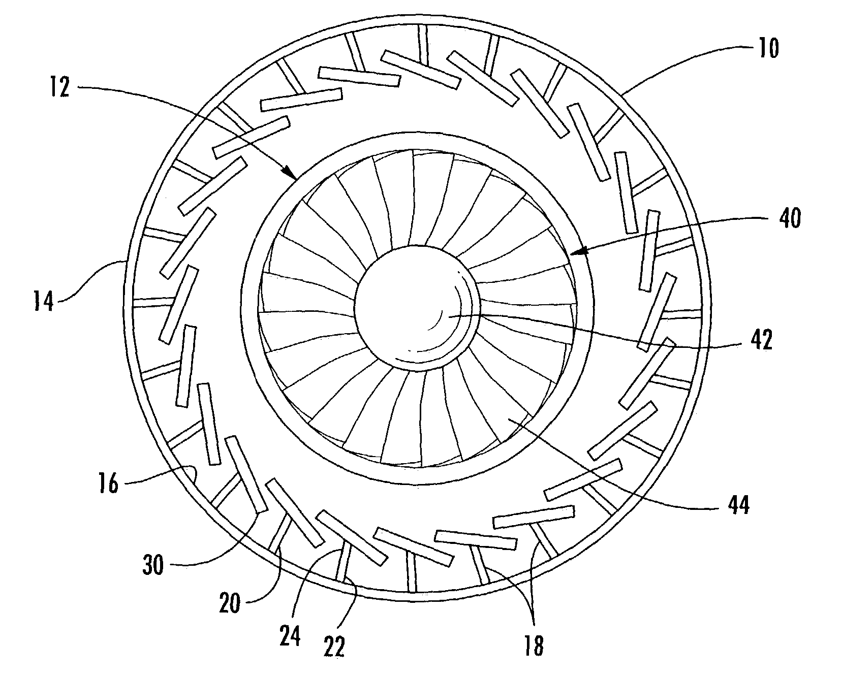
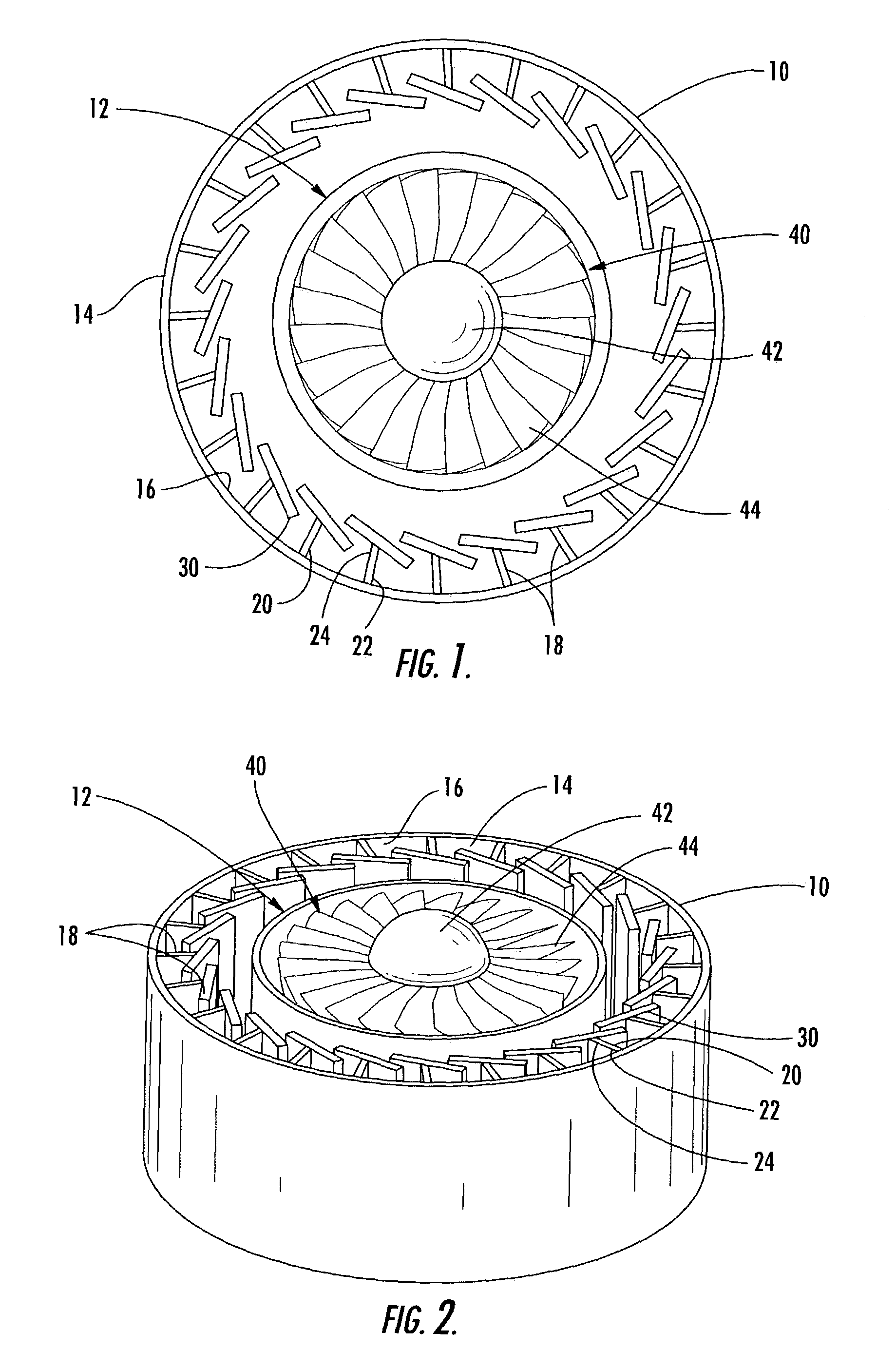
[0019]Referring now to the figures and, in particular, FIGS. 1 and 2, there is shown a containment device 10 for retaining structural fragments, foreign objects, and other material, referred to generally as debris material, traveling from or through a rotary device 12. The containment device 10 of the present invention can be used with a variety of rotary devices 12. For example, the rotary device 12 can be an energy storage unit, a transmission, a gearbox, a turbine, or another rotary device that includes at leas...


PUM


Abstract

A containment device for use in retaining debris material traveling radially outward in a rotary device is provided as is a turbine having a containment device. The containment device includes an outer ring that extends generally circumferentially and defines an inner surface directed radially inward. A plurality of energy absorption elements are disposed on the inner surface of the outer ring. Each absorption element extends both radially inward and circumferentially so that each absorption element is configured to be plastically deformed radially outward by debris material impacting the absorption element. Each absorption element can include a base and a cap, the base extending in a generally radial direction and the cap being connected to the radially inward end of the respective base and defining an angle therewith.

Description

BACKGROUND OF THE INVENTION[0001]1) Field of the Invention[0002]The present invention relates to a device for containing material released by or into a rotary device such as a turbine.[0003]2) Description of Related Art[0004]Many rotary devices include a surrounding structure for containing fragments that are released by the device during a failure. For example, a conventional rotary device such as a flywheel has a housing that surrounds the flywheel. The housing can be a strong, rigid structure designed to withstand the impact of pieces, or fragments, of the flywheel that are released if the flywheel breaks while operating at a high rotational speed. Due to the high speed and / or mass of conventional rotary devices, the fragments released during failure can have significant kinetic energy. Therefore, the housing must be strong in order to contain the fragments, typically requiring a thick housing that adds weight and cost to the device.[0005]U.S. Pat. No. 6,182,531, titled “Containm...

Claims


Application Information

Patent Timeline
Patent Type & Authority Patents(United States)
IPC IPC(8): F01D21/00F01D21/04F01D25/24
CPCF01D21/045F01D25/24Y10T74/2191
Inventor GABRYS, JONATHAN W.FELKER, CHRISTOPHER J.
Owner THE BOEING CO
Why Eureka
Try Eureka