Spinal osteosynthesis system for anterior fixation

a technology of spinal osteosynthesis and anterior fixation, which is applied in the field of spinal osteosynthesis systems, can solve the problems of difficult use of systems based on plates, inability to treat scoliosis with this type of implant, and simple vertebraectomies, and achieves good stability of the system on the spine. , the effect of easy fitting

Inactive Publication Date: 2006-03-07
STRYKER EURO OPERATIONS HLDG LLC
View PDF39 Cites 164 Cited by
  • Summary
  • Abstract
  • Description
  • Claims
  • Application Information

AI Technical Summary

Benefits of technology

[0005]An object of the invention is to make available a spinal osteosynthesis system of a different type, adapted for anterior fixation, easy to fit, ensuring good stability of the system on the spine, and compatible with being fitted via the endoscopic route.

Problems solved by technology

Because of their bulk, the systems based on plates are difficult to use, if they can be used at all, via the endoscopic route.
Moreover, their limited size (length) means that they can only be used for simple vertebrectomies involving a single vertebra, or perhaps two.
It is impossible to treat scoliosis with this type of implant.
Finally, the plates are difficult to adapt to the morphology of the vertebra in which they are anchored.
Moreover, the systems based on rods generally comprise fairly voluminous connectors which cannot always be used via the endoscopic route.
However, this connector, while well suited for posterior fixation of the spine on the vertebral pedicles, does not ensure sufficient stability with a view to anterior fixation of the spine.

Method used


Image

  • Spinal osteosynthesis system for anterior fixation
  • Spinal osteosynthesis system for anterior fixation
  • Spinal osteosynthesis system for anterior fixation

Examples


Embodiment Construction

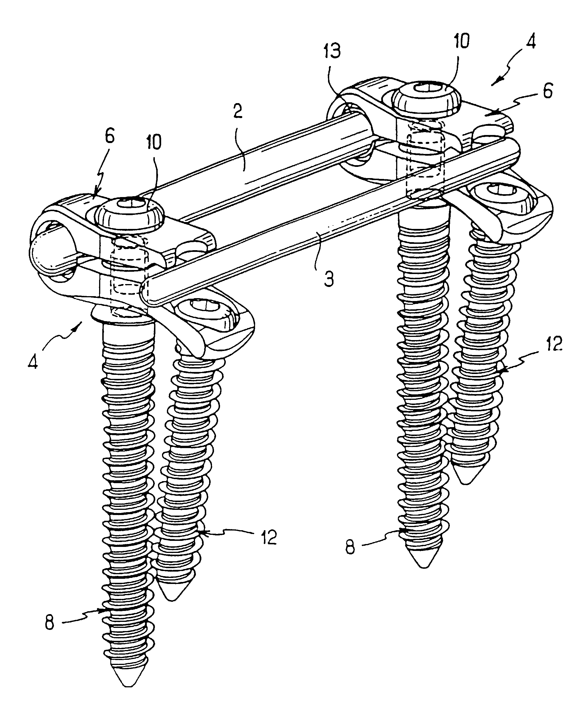
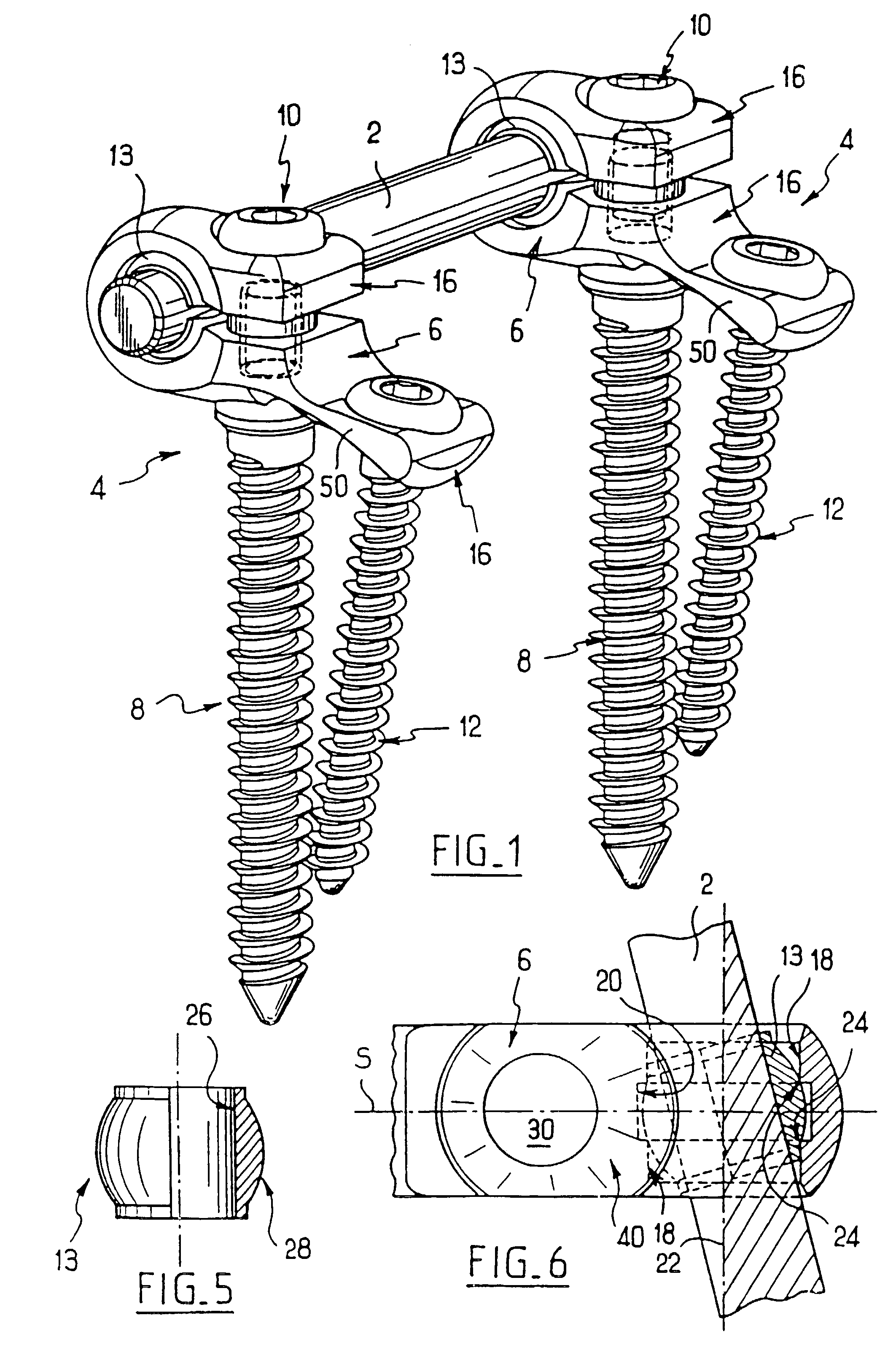
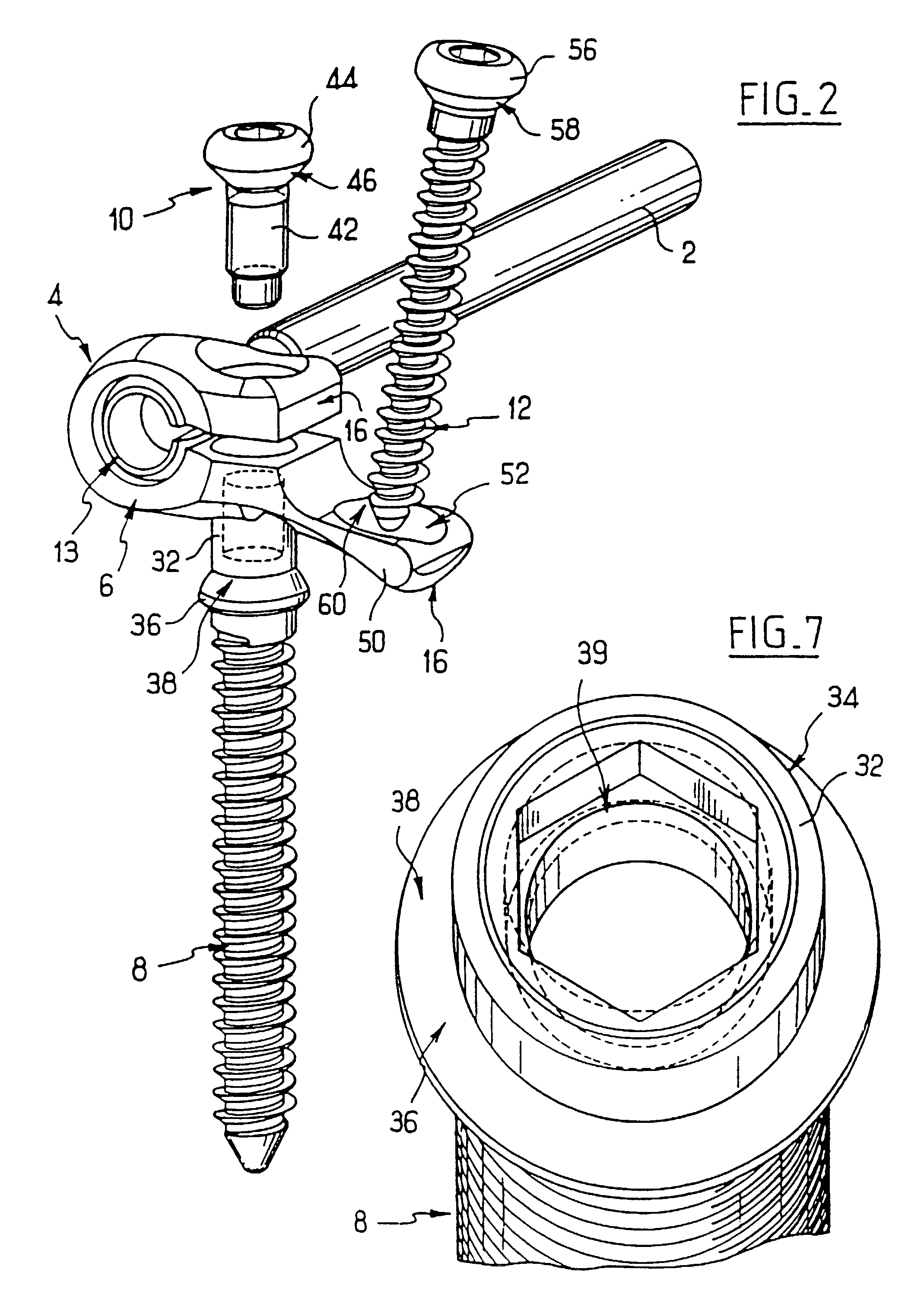
[0050]Referring to FIGS. 1 to 8, the system according to the invention comprises, in the first embodiment, an elongate connection rod 2 of circular cross section and several connector sub-assemblies 4 which can be fixed to the latter. Each of these sub-assemblies, of which two can be seen in FIG. 1 and of which one can be seen in FIG. 2, comprises a connector 6, a first vertebral screw or main screw 8, a clamping screw 10, a second vertebral screw or secondary screw 12, and a ring 13.

[0051]Referring to FIGS. 3 and 4, the connector 6 includes two branches 16 extending opposite to and at a distance from each other, giving the connector a general U-shaped profile. The connector 6 includes a plane of symmetry S perpendicular to the width of the branches 16 and parallel to their length. Referring to FIG. 6, at the point of origin of the branches 16 the connector has two cylindrical and coaxial inner faces 18, 20 with axis 22 perpendicular to the plane S and with different radii, the face...


PUM


Abstract

The invention concerns a backbone osteosynthesis system comprising an elongated element, a vertebral screw, and a connecting element comprising two branches for clamping between them the linking element, at least one first branch being capable of being engaged onto the screw. The system comprises a second vertebral screw, the first branch having an extension capable of being engaged onto the second screw. The system may comprise a second elongated linking element.

Description

CROSS-REFERENCE TO RELATED APPLICATIONS[0001]This application is a continuation of U.S. application Ser. No. 09 / 674,207 filed on Jan. 30, 2001, now U.S. Pat. No. 6,569,164, which application is the National Stage of International Application No. PCT / FR99 / 01019, filed Apr. 29, 1999, the disclosure of which is hereby incorporated by reference herein.BACKGROUND OF THE INVENTION[0002]The invention concerns spinal osteosynthesis systems, in particular for anterior fixation.[0003]Spinal osteosynthesis systems for anterior fixation are known in which the connection elements are formed by plates, and others are known in which the connection elements are formed by rods. Because of their bulk, the systems based on plates are difficult to use, if they can be used at all, via the endoscopic route. Moreover, their limited size (length) means that they can only be used for simple vertebrectomies involving a single vertebra, or perhaps two. It is impossible to treat scoliosis with this type of imp...

Claims


Application Information

Patent Timeline
Patent Type & Authority Patents(United States)
IPC IPC(8): A61B17/56A61B17/70A61B17/58
CPCA61B17/7037A61B17/7044A61B17/7041A61B17/704
Inventor ASSAKER, RICHARDCONCHY, FREDERICLE COUEDIC, REGIS
Owner STRYKER EURO OPERATIONS HLDG LLC
Why Eureka
Try Eureka