
System and method of using multiple representations per object in computer graphics

a computer graphics and object technology, applied in the field of computer graphics system and method, can solve the problems of large amount of dicing, inability to achieve typical object scenes, and inability to use typical objects, etc., and achieve the effect of coarse resolution

Inactive Publication Date: 2006-03-07
NVIDIA CORP
View PDF4 Cites 31 Cited by
  • Summary
  • Abstract
  • Description
  • Claims
  • Application Information

AI Technical Summary

Benefits of technology

[0015]The present invention includes a system and method of shading a plurality of objects included in an object scene. The system and method typically includes creating a plurality of representations for the object. After creating the plurality of representations, a plurality of primary positions are established on one of the representations. Shading positions on one or more other representation

Problems solved by technology

If the primitive is much larger, for example, a large amount of dicing may be required.
But this is not usually practical for typical object scenes.
First, intersecting the number of rays necessary to recreate the sufficient amount of primitive detail requires too much processing time.
Second, rays are typically cast without consideration of the primitives that may or may not be intersected, so there is no assurance that all visible complexities are intersected by any rays.
As the complexity of a polygonal mesh decreases, so does the amount of processing time required to determine whether a ray intersects the polygonal mesh.
Prior art systems that do combine the more beneficial aspects of a REYES renderer and a ray tracing renderer (albeit inefficiently) cast rays from positions on polygonal meshes suitable for a REYES renderer (e.g., polygonal meshes comprising polygons approximately equal in size to a pixel) for intersection with polygonal meshes suitable for a ray tracing renderer (e.g., polygonal meshes comprising polygons sized by reference to a primitive represented by the polygonal meshes).
Often times, however, these rays invalidly intersect or fail to intersect these primitives because of the differences between how polygonal meshes suitable for a REYES renderer are created and how polygonal meshes suitable for a ray tracing renderer are created.
So in these prior art systems that combine the more beneficial aspects of a REYES renderer and a ray tracing renderer (albeit inefficiently) rays are cast from vertices.
And again, a REYES renderer does not maintain or access all of the polygonal meshes created for computer animated video or images at any one time.
As a result, rays often invalidly intersect other primitives in an object scene.

Method used


Image

  • System and method of using multiple representations per object in computer graphics
  • System and method of using multiple representations per object in computer graphics
  • System and method of using multiple representations per object in computer graphics

Examples


Embodiment Construction

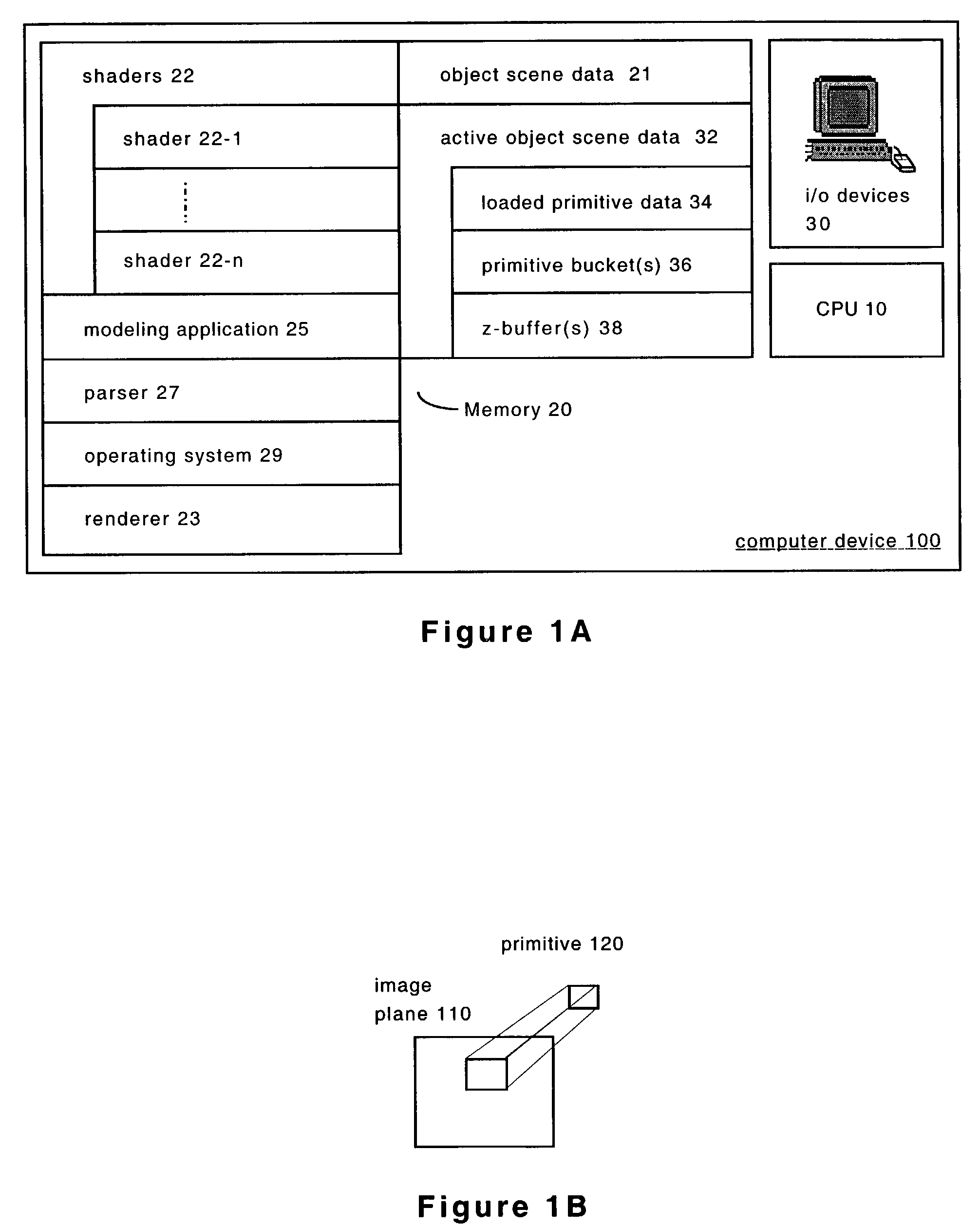
[0029]FIG. 1A shows a computer device 100 configured to execute the various embodiments of the present invention described below. Included in the computer device 100 is a central processing unit (CPU) 10, a memory 20, and i / o devices 30. The CPU 10 executes instructions as directed by the operating system 29 and other programs maintained in the memory 20 and sends control signals to various hardware components included in the computer device 100. The memory 20 typically comprises high speed random access memory as well as non-volatile storage such as disk storage.

[0030]Object scene data 21 is typically static information maintained in the non-volatile section of the memory 20. The object scene data 21 may be maintained in any type of data structure (e.g., database, flat file system, etc.) without departing from the scope of the present invention. The object scene data 21 describes one or more object scenes. An object scene is one of many that, for example, comprise the scenes of com...


PUM


Abstract

The present invention is related to rendering computer animated video and / or images generally, and to efficiently intersecting rays with an object scene while shading complex object representations. The present invention, generally, includes creating a plurality of representations for the object. After creating the plurality of representations, a plurality of primary positions are established on one of the representations. Shading positions on one or more other representations included in the plurality of representations are then established by reference to the primary positions. These shading positions correspond to the plurality of primary positions and each of these representations has a coarser resolution than the representation with the primary positions. Shading values for the shading positions are the computed and applied to the plurality of primary positions.

Description

[0001]The present invention is related to rendering computer animated video and / or images generally, and to using multiple representations per object specifically.RELATED APPLICATIONS[0002]This application is related to, and incorporates herein by reference, a U.S. patent application bearing Ser. No. 09 / 865,990, entitled “SYSTEM AND METHOD OF LINE SAMPLING OBJECT SCENE INFORMATION”, and commonly assigned with the present invention. This application is also related to, and incorporates herein by reference, a U.S. patent application Ser. No. 10 / 157,579, filed on May 28, 2002, entitled “SYSTEM AND METHOD RELATED TO DATA STRUCTURES IN THE CONTEXT OF A COMPUTER GRAPHICS SYSTEM”, and commonly assigned with the present invention.BACKGROUND OF THE INVENTION[0003]A REYES image rendering architecture is a system for computing computer animated video or images. The details of an exemplary REYES image rendering architecture are described in detail by Robert L. Cook, et al. in “The Reyes Image R...

Claims


Application Information

Patent Timeline
IPC IPC(8): G06T15/60G06T15/50
CPCG06T15/80
Inventor PHARR, MATTHEW MILTONVEACH, ERIC
Owner NVIDIA CORP
Learn More