Compact projection lenses for use with large format pixelized panels

a projection lens and large-format technology, applied in the field of projection lenses, can solve the problems of lateral color, i.e., the variation of magnification with color, and the inability to perform accommodation, and achieve the effect of not being able to smooth the adjustment of size across the full field of view

Inactive Publication Date: 2006-03-07
3M INNOVATIVE PROPERTIES CO
View PDF14 Cites 3 Cited by
  • Summary
  • Abstract
  • Description
  • Claims
  • Application Information

AI Technical Summary

Problems solved by technology

Lateral color, i.e., the variation of magnification with color, is particularly troublesome since it manifests itself as a decrease in contrast, especially at the edges of the field.
With a pixelized panel, however, such an accommodation cannot be performed because the image is digitized and thus a smooth adjustment in size across the full field of view is not possible.
The requirement for a large FOV makes it even more difficult to correct the lateral color of the lens.
Achieving wide fields of view in the direction of the lens' long and short conjugates, while still maintaining high levels of aberration correction, is technically challenging.
To do so while minimizing the size of the projection lens and the number of optical components used in the lens is even more demanding.

Method used


Image

  • Compact projection lenses for use with large format pixelized panels
  • Compact projection lenses for use with large format pixelized panels
  • Compact projection lenses for use with large format pixelized panels

Examples


examples

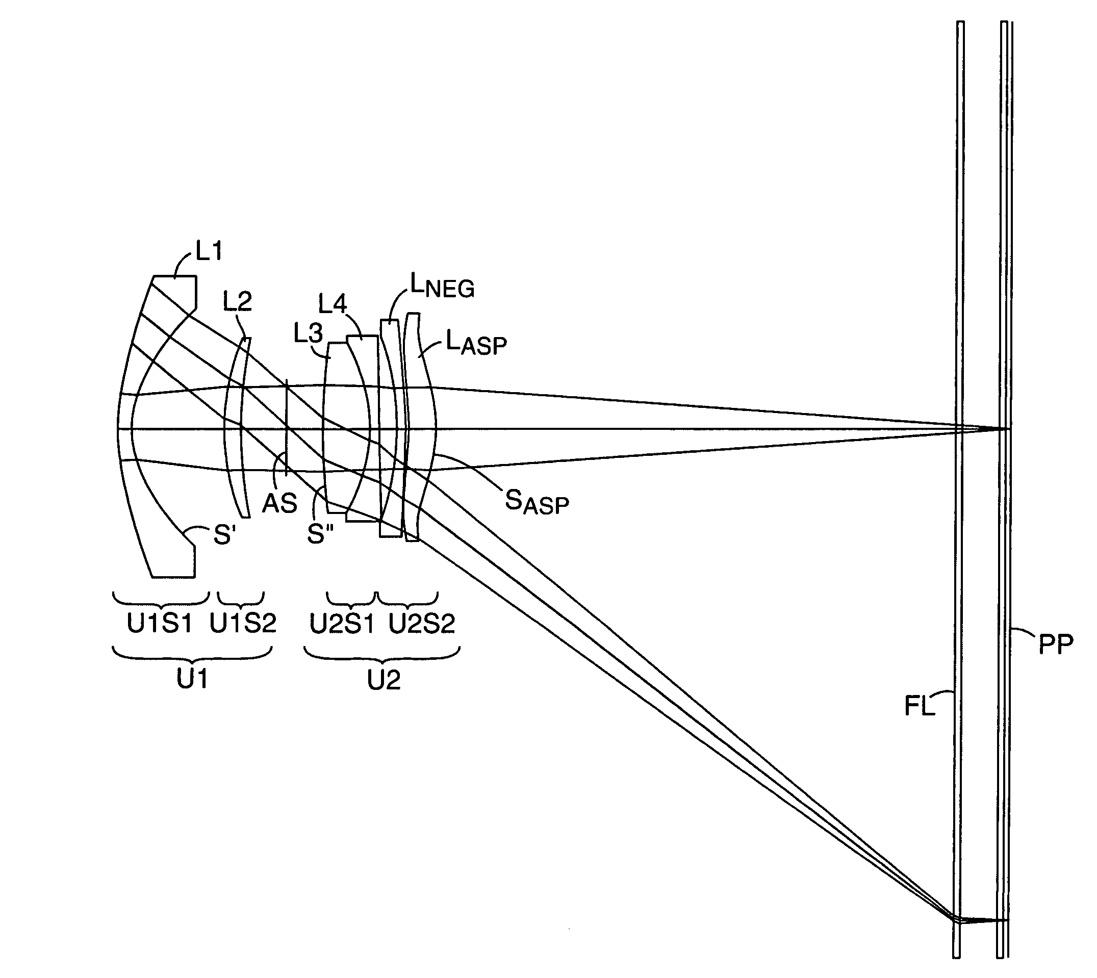
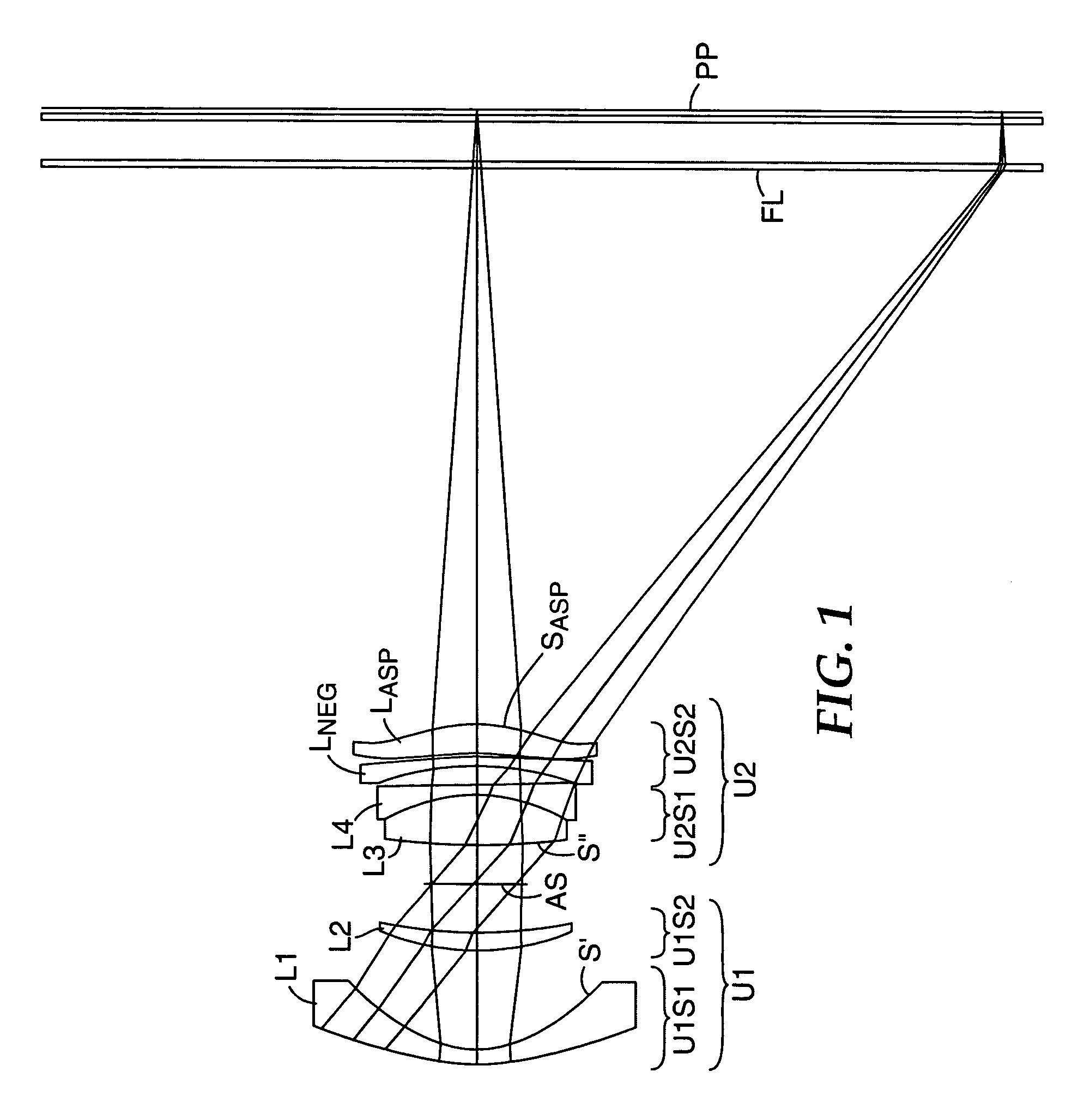
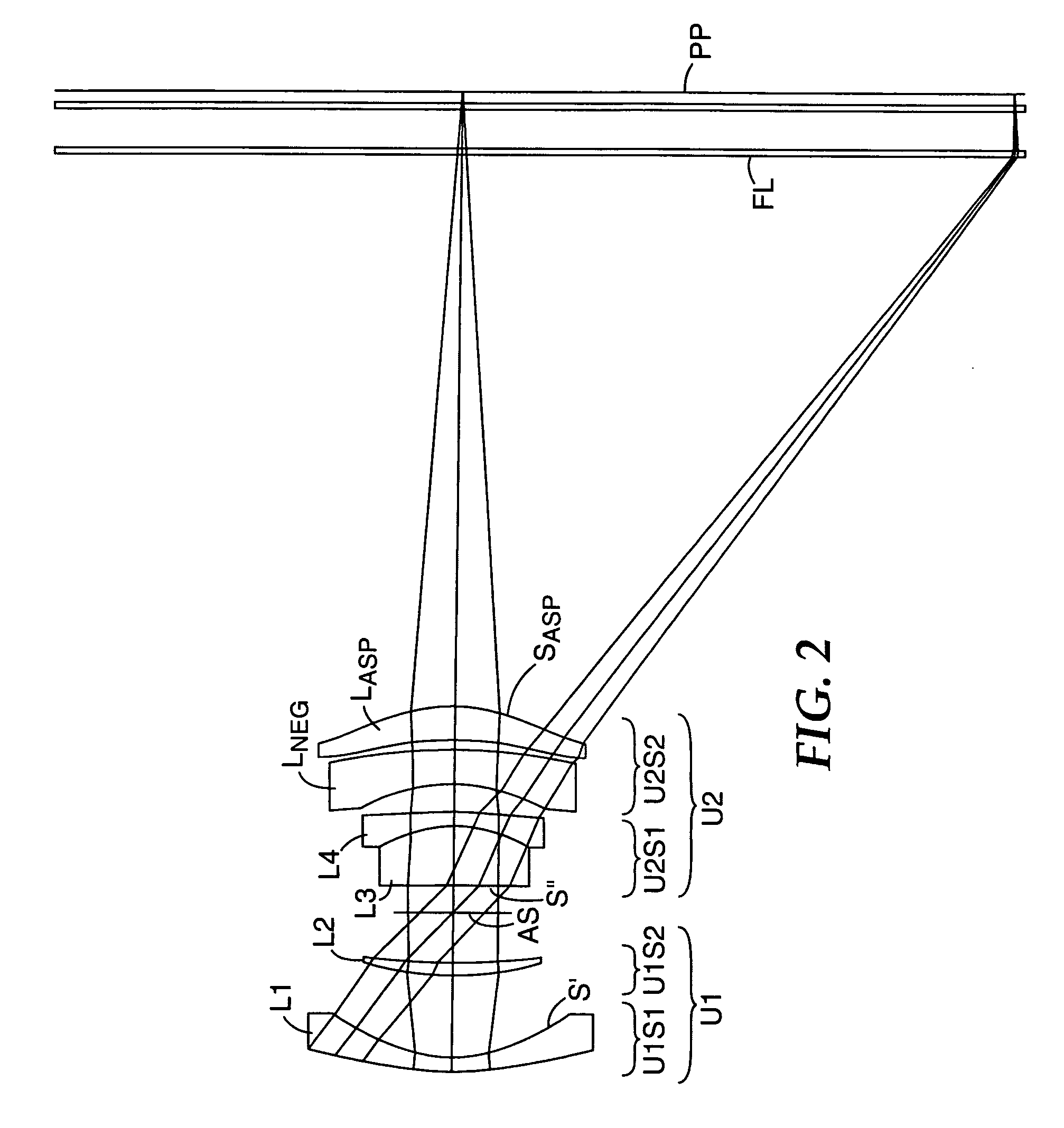
[0074]FIGS. 1–4 and Tables 1–4 illustrate representative projection lenses constructed in accordance with the invention. The lenses of Examples 1 and 2 were designed for use with pixelized panels having diagonals of 15 inches (380 mm), while those of Examples 3 and 4 were designed for panel diagonals of 13 inches (330 mm) and 10 inches (250 mm), respectively. FIG. 1 is drawn based on the prescription of Table 1A. Table 1B shows a variation of this prescription which has a somewhat larger space between U2S1 and U2S2 to facilitate assembly of the lens. Although not identical to the prescription of Table 1B, FIG. 1 shows the general structure of the lens of this table.

[0075]OHARA designations are used in the prescriptions of Tables 1–4 for the various glasses employed in the lens systems. Equivalent glasses made by other manufacturers (e.g., HOYA or SCHOTT) can be used in the practice of the invention. Industry acceptable materials are used for the plastic elements.

[0076]The aspheric c...


PUM


Abstract

Projection lenses for use with pixelized panels (PP) are provided. The projection lenses have first and second lens units (U1,U2), with the first lens unit having a negative or weakly positive power and the second lens unit having a positive power. The second lens unit has first and second subunits (U2S1 and U2S2) which provide positive power followed by negative power. The second subunit (U2S2) of the second unit (U2), in turn, has negative power followed by positive power. In this way, an overall short projection lens (e.g., BRL / f0≦0.9) along with small lens elements (e.g., CAmax / f0≦0.8) can be achieved.

Description

FIELD OF THE INVENTION[0001]This invention relates to projection lenses and, in particular, to projection lenses for use in forming an image of an object composed of pixels, such as, a DMD, a reflective LCD, a transmissive LCD, or the like. The lenses are particularly well-suited for use with large format transmissive LCDs, e.g., LCDs having a diagonal on the order of 10 inches (250 millimeters) or more.BACKGROUND OF THE INVENTION[0002]A. Definitions[0003]As used in this specification and in the claims, the following terms shall have the following meanings:[0004](1) Optical Component.[0005]An optical component is a component which has optical power and / or corrects one or more monochromatic and / or one or more chromatic aberrations and which requires separate mounting and alignment from other components of the projection lens.[0006]As illustrated by the examples present below, optical components include, for example, single lens elements and cemented doublets. Projection lenses having...

Claims


Application Information

Patent Timeline
Patent Type & Authority Patents(United States)
IPC IPC(8): G02B9/00G02B9/60G02B13/16G02B13/18
CPCG02B9/60G02B13/18G02B13/16
Inventor CANNON, BRUCE L.
Owner 3M INNOVATIVE PROPERTIES CO
Why Eureka
Try Eureka