
3PI algorithm for spiral CT

a spiral ct and algorithm technology, applied in tomography, applications, instruments, etc., can solve the problems of consuming a lot of computer power, affecting the patient's recovery, so as to achieve the effect of slowing down the patien

Inactive Publication Date: 2006-03-07
UNIV OF CENT FLORIDA RES FOUND INC
View PDF3 Cites 10 Cited by
  • Summary
  • Abstract
  • Description
  • Claims
  • Application Information

AI Technical Summary

Benefits of technology

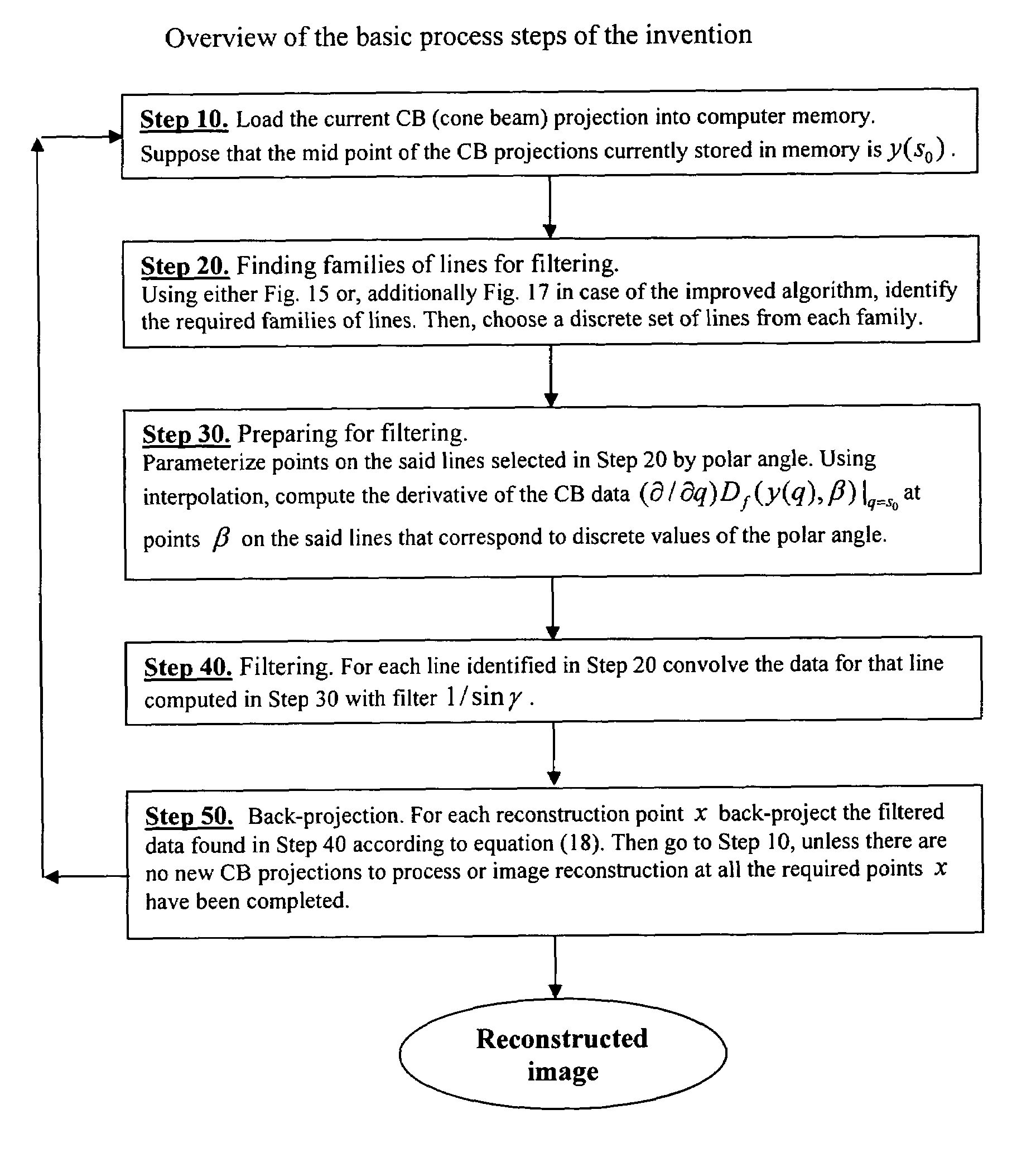
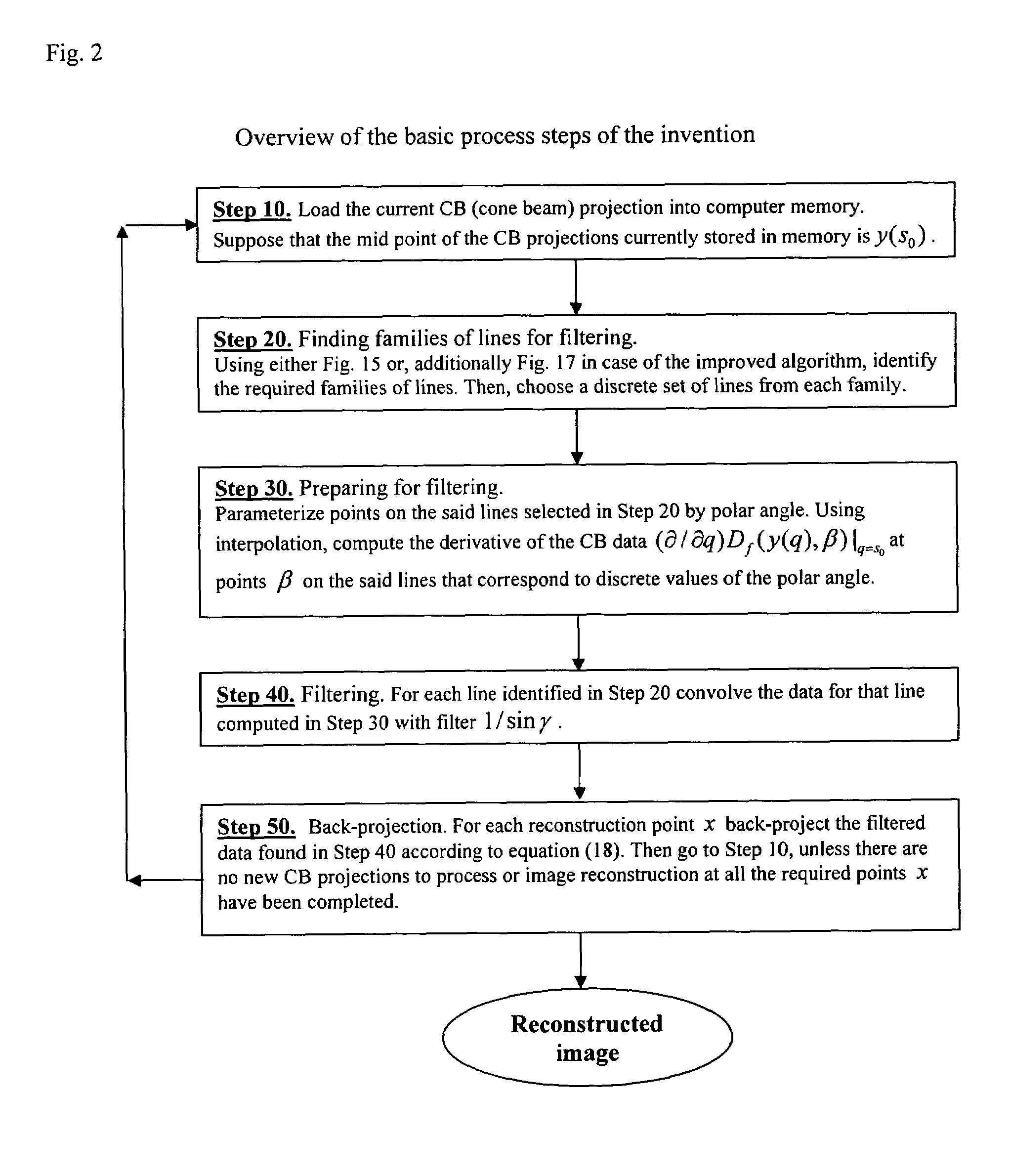
[0007]A primary objective of the invention is to provide 3PI algorithms for reconstructing images of objects that have been scanned in a spiral fashion with two-dimensional detectors. For image reconstruction at any given voxel these algorithms require a longer section of the spiral than the 1PI algorithms of U.S. patent application Ser. No. 10 / 143,160 filed May 10, 2002, now U.S. Pat. No. 6,574,299, which is incorporated by reference, which claims the benefit of priority to U.S. Provisional Application 60 / 312,827 filed Aug. 16, 2001. Consequently, the new algorithms allow to slow the patient down by about a factor of three, but still use the same size detector array.

Problems solved by technology

In CT there have been significant problems for image reconstruction especially for two-dimensional detectors.
However, exact algorithms can be known to take many hours to provide an image reconstruction, and can take up great amounts of computer power when being used.
These algorithms can require keeping considerable amounts of cone beam projections in memory.
Additionally, some exact algorithms can require large detector arrays to be operable and can have limits on the size of the patient being scanned.
However, even under the ideal circumstances they produce an approximate image that may be similar to but still different from the exact image.
In particular, Approximate algorithms can create artifacts, which are false features in an image.
Under certain circumstances these artifacts could be quite severe.
However, rapid motion of the patient is very impractical for obvious reasons.
This leads to undesirable consequences: part of the x-ray dose is wasted, discretization artifacts are enhanced, noise stability is reduced, etc.

Method used


Image

  • 3PI algorithm for spiral CT
  • 3PI algorithm for spiral CT
  • 3PI algorithm for spiral CT

Examples


Embodiment Construction

[0035]Before explaining the disclosed embodiments of the present invention in detail it is to be understood that the invention is not limited in its application to the details of the particular arrangements shown since the invention is capable of other embodiments. Also, the terminology used herein is for the purpose of description and not of limitation.

[0036]This invention is a continuation-in-part of U.S. patent application Ser. No. 10 / 143,160 filed May 10, 2002, now U.S. Pat. No. 6,574,299, which is incorporated by reference, which claims the benefit of priority to U.S. Provisional Application 60 / 312,827 filed Aug. 16, 2001.

[0037]The invention will now be described in more detail.

Theoretical Background

[0038]First we introduce the necessary notations. Let

C:={y∈R3:y1=R cos(s), y2=R sin(s), y3=s(h / 2π), s∈R},  (1)

where h>0 be a spiral, and U be an open set strictly inside the spiral:

Ū⊂{x∈R3:x12+x22<r2}, 0<r<R,  (2)

S2 is the unit sphere in R3, and Df⁡(y,β):=∫0∞⁢f⁡(y+β⁢⁢t)⁢⁢ⅆt...


PUM


Abstract

Methods and systems for reconstructing images of moving objects being spirally scanned with two dimensional detectors with a 3PI algorithm. The moving objects can be scanned at a rate of up to approximately three times slower than those of pre-existing systems. In a preferred embodiment, the invention allows for a patient on a table moving through a spiral scanner to be slowed down by a factor of up to three, and still use the same size detector array as those in existing spiral scanning systems.

Description

[0001]This invention claims the benefit of priority to U.S. Provisional Application Ser. No. 60 / 430,802 filed, Dec. 4, 2002, and is a Continuation-In-Part of U.S. patent application Ser. No. 10 / 389,534 filed Mar. 14, 2003, now U.S. Pat. No. 6,804,321, which is a Continuation-In-Part of Ser. No. 10 / 389,090 filed Mar. 14, 2003, now U.S. Pat. No. 6,771,733, which is a Continuation-In-Part of Ser. No. 10 / 143,160 filed May 10, 2002 now U.S. Pat. No. 6,574,299, which claims the benefit of priority to U.S. Provisional Application 60 / 312,827 filed Aug. 16, 2001.FIELD OF INVENTION[0002]This invention relates to computer tomography, and in particular to processes, methods and systems for reconstructing three-dimensional images from the data obtained by spiral scans using 3PI algorithm.BACKGROUND AND PRIOR ART[0003]Over the last thirty years, computer tomography (CT) has gone from image reconstruction based on scanning in a slice-by-slice process to spiral scanning. From the 1970s to 1980s the...

Claims


Application Information

Patent Timeline
IPC IPC(8): A61B6/03A61B6/00G01N23/00G06T11/00G21K1/12H05G1/60
CPCA61B6/032A61B8/483A61B6/027G06T11/006G01N2223/3304Y10S378/901G06T2211/416G06T2211/421
Inventor KATSEVICH, ALEXANDER
Owner UNIV OF CENT FLORIDA RES FOUND INC
Learn More