Radiographic image composition and use

a radiographic image and composite technology, applied in image enhancement, image analysis, instruments, etc., can solve the problems of more acute, unusable overlap area, creation of artifacts, etc., and achieve the effect of eliminating any visible overlap area

Inactive Publication Date: 2006-03-07
CANON KK
View PDF18 Cites 37 Cited by
  • Summary
  • Abstract
  • Description
  • Claims
  • Application Information

AI Technical Summary

Benefits of technology

[0020]Advantageously, artifacts (e.g., banding in region 206 of FIG. 2), which are produced using other blending techniques, are not produced in the blending performed using the present invention. Accordingly, a composite image, which is generated using the present invention, provides a more useful examination and / or diagnostic instrument, and also eliminates any visible overlap area.

Problems solved by technology

However, the overlapped image portions could differ so significantly that the overlapped portion is unusable.
A problem that exists when stitching images concerns blending the pixel values (e.g., greylevel pixel values) along a seam or stitching line between adjacent images in order to blend the images.
However, the mismatch between the pixel values of the adjacent images can be such that blending the images becomes difficult and can result in the creation of artifacts.
In other words, the problems that occur when blending radiographic images are more acute than with optical images, since the contrast (i.e., the degree to which the pixel values differ) between the images can be more extreme due at least in part to the variance in the paths of the rays at the stitching point of adjacent images.
As a result, as images 104 and 105 are blended, blending artifacts can be created, which reduce the usefulness of the composite image.
Composite image 211 was generated using a blending technique, which was determined to be unsatisfactory.
This blending technique is considered to be unsatisfactory, because artifacts are created as a result, which reduces the usefulness of composite image 211.
Consequently, blending of the image panes is unsatisfactory, since artifacts are likely to result.
In a composite x-ray image, a visible overlap area limits the usefulness of the composite image.

Method used


Image

  • Radiographic image composition and use
  • Radiographic image composition and use
  • Radiographic image composition and use

Examples


Embodiment Construction

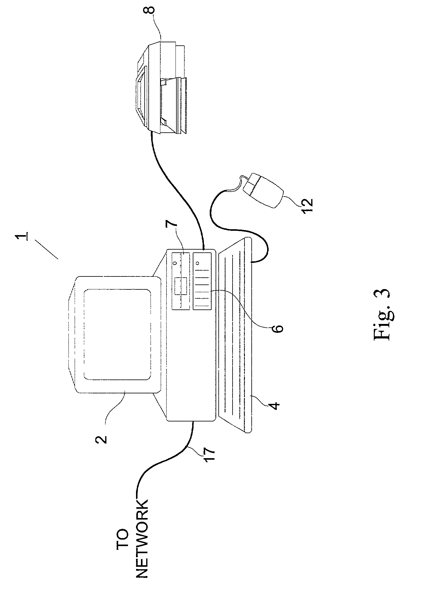
[0034]FIG. 3 is an outward view of representative computing hardware embodying the present invention. It should be apparent that the present invention is not limited to use with the computing hardware shown in FIG. 3, and that other computing hardware configurations may be used with the present invention.

[0035]Shown in FIG. 3 are computer 1 executing an operating system, such as Microsoft Windows98®, display monitor 2 for displaying text and images to a user, keyboard 4 for entering text and commands into computer 1, and mouse 5 for manipulating and for selecting objects displayed on display monitor 2. Also included with computer 1 are fixed disk drive 6, in which are stored application programs, such as digital image processing, word processing, graphics, and other applications as well as data files, and device drivers for controlling peripheral devices attached to computer 1, floppy disk drive 7 for use in reading data from and writing data to floppy disks inserted therein. Data a...


PUM


Abstract

The present invention concerns the blending of plural x-ray images to form a blended composite image wherein in blending the images, a stitching boundary adjustment is determined for use in adjusting boundary pixels of the composite image, and an adjustment for other pixels that are located at some distance from the boundary is determined, wherein the adjustment for the other pixels depends on the stitching boundary adjustment and on values of the boundary pixels.

Description

BACKGROUND OF THE INVENTION[0001]1. Field of the Invention[0002]The present invention relates to formation of a composite radiographic image from plural radiographic images, and more particularly to conforming the boundaries between the images so as to form a useful composite image.[0003]2. Description of the Related Art[0004]Radiographic imaging, such as x-ray imaging, has long been used for examination and diagnostic purposes. Where successive images are taken in order to provide a continuing view of a subject, it would be beneficial to be able to form a composite image from the successive images.[0005]Prior to the digital age, radiographers manually created a composite image from successive images by laying a portion of one image over another image, attempting to visually align the images, and then taping the images together. In the resulting composite image, there are overlapped portions of the individual images. The composite image was then typically “read” using a light box. H...

Claims


Application Information

Patent Timeline
Patent Type & Authority Patents(United States)
IPC IPC(8): G06K9/00G06T5/00G06T5/50
CPCG06T3/4038G06T5/50G06T2207/30008G06T2207/20221G06T2207/10116
Inventor BOJER, IVANBERESTOV, ALEXANDER LEONIDOVICHSPAULDING, AUTUMN CLAIRE
Owner CANON KK
Why Eureka
Try Eureka