
Integrateable band filter using waveguide grating routers

a waveguide grating router and integrated technology, applied in the field of optical band filters, can solve the problems of high cost, laborious hand assembly, and high loss of thin-film interference filters, and achieve the effect of convenient fabrication

Active Publication Date: 2006-03-07
WSOU INVESTMENTS LLC +1
View PDF8 Cites 5 Cited by
  • Summary
  • Abstract
  • Description
  • Claims
  • Application Information

AI Technical Summary

Benefits of technology

[0009]In an alternate embodiment of the present invention, a planar lightwave circuit includes at least two substantially identical band filters of the present invention constructed on a single chip to save cost. In one embodiment, the planar lightwave circuit has a size equal to 8.7 cm×1.0 cm.

Problems solved by technology

Thin-film interference filters typically have very low losses however, they require expensive hermetic packages and tedious hand assembly.
Thin-film interference filters also typically exhibit significant chromatic dispersion, they require more than ten cavities to achieve sharp passband corners, and they typically require a cascade to demultiplex more than two bands.
This type of band filters can be dispersion-free and can de / multiplex more than two bands without a cascade, however, they exhibit more loss than their thin-film counterparts.
Bulk grating band filters also comprise large form factors, and, like thin-film filters, require expensive hermetic packages and tedious hand assembly.
However, the previously proposed band filters based on PLCs (also known as MZI-based filters) become exceedingly large in form factor and are very demanding to de / multiplex more than four bands and / or to achieve sharp passband corners.

Method used


Image

  • Integrateable band filter using waveguide grating routers
  • Integrateable band filter using waveguide grating routers
  • Integrateable band filter using waveguide grating routers

Examples


Embodiment Construction

[0018]Although various embodiments of the present invention herein are being described with respect to a 1×3 optical band filter, it will be appreciated by those skilled in the art informed by the teachings of the present invention that the concepts of the present invention are applicable to band filters comprising substantially any number or combination of inputs and outputs.

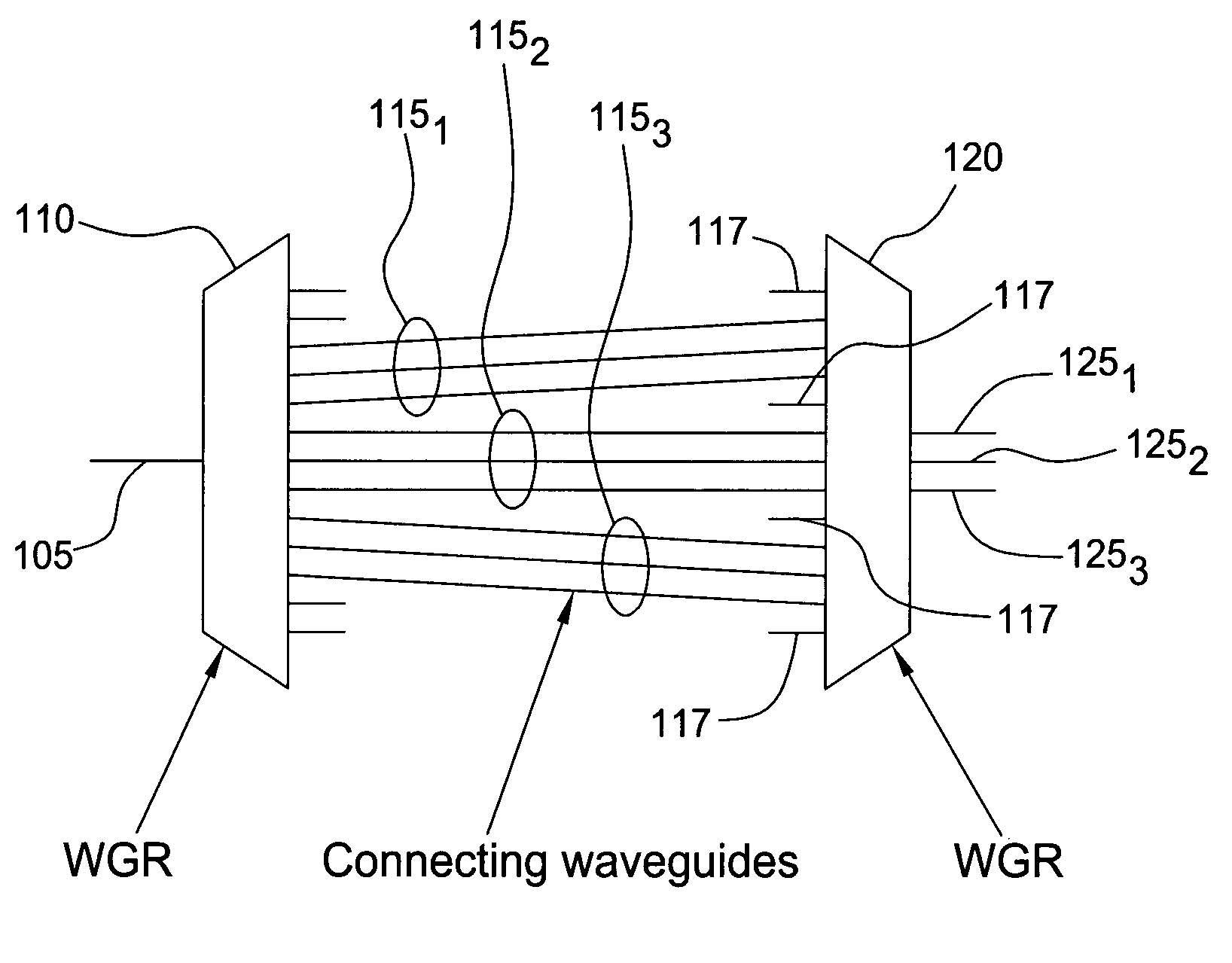
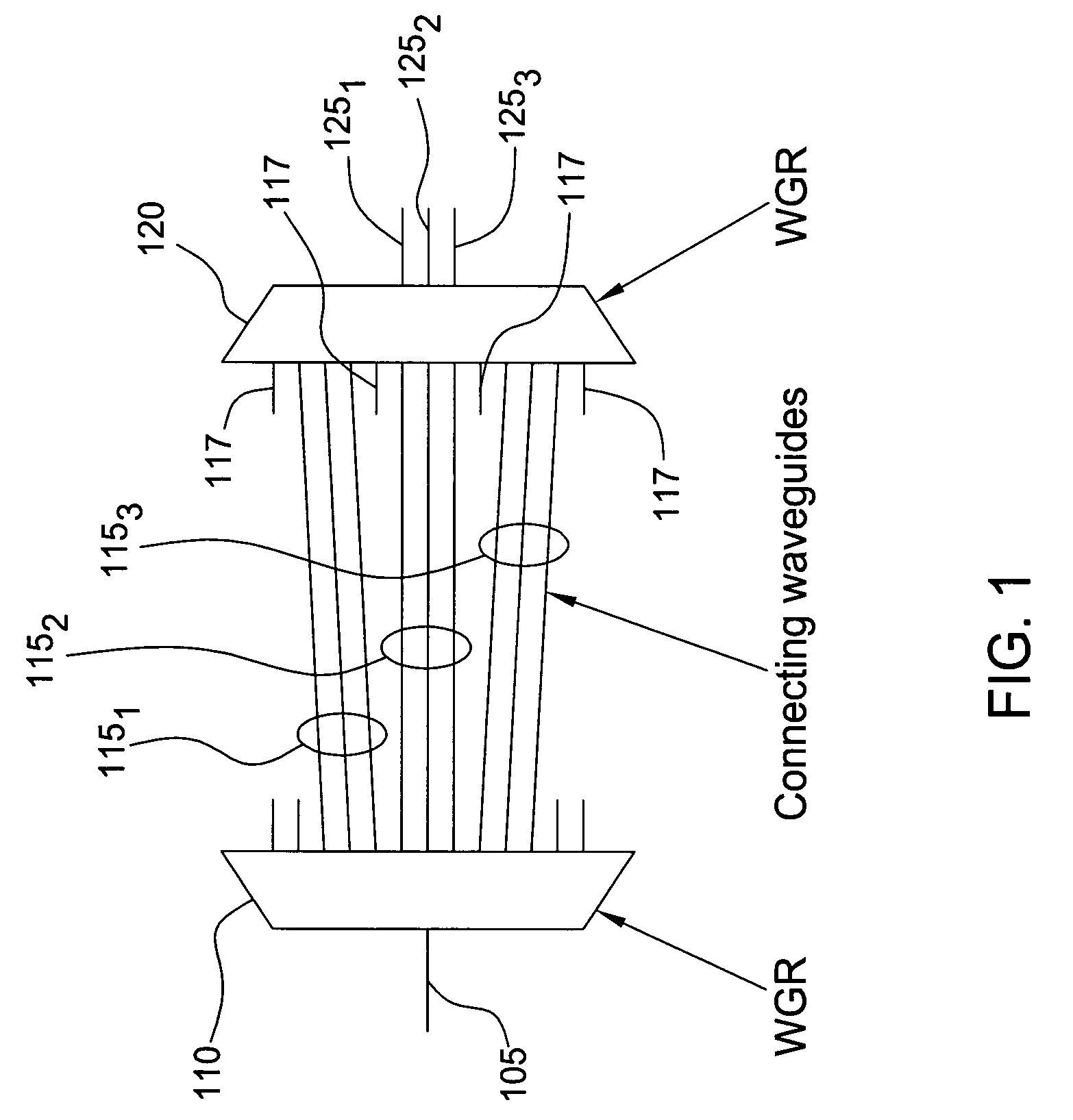
[0019]FIG. 1 depicts a high level block diagram of one embodiment of a band filter in accordance with the present invention. The band filter 100 of FIG. 1 illustratively comprises one input waveguide 105, an input waveguide grating router (WGR) 110, a plurality of connecting waveguides 115, a plurality of dummy waveguides 117, an output WGR 120 and three output waveguides 1251, 1252 and 1253 (collectively output waveguides 125). Although in FIG. 1, the band filter 100 is being depicted and described as comprising one input waveguide 105 and three output waveguides 1251, 1252 and 1253 and as such functioning as ...


PUM


Abstract

The inventors propose herein a novel band filter design for planar lightwave circuits. In one embodiment of the present invention, the band filter includes two waveguide grating routers connected by sets of substantially equal path length waveguides within each set separated on one side, wherein the waveguides of each set are formed such that optical signals having overlapping frequency ranges are propagated through adjacent waveguides. In addition, the waveguides of each set are spaced at their connection to the second waveguide grating router such that optical signals with predetermined optical frequency ranges are routed to selected, respective output ports. Some of the advantages of this novel band filter include compactness, sharp passband corners, and a lack of chromatic dispersion.

Description

CROSS-REFERENCE TO RELATED APPLICATIONS[0001]This patent application is related to U.S. Pat. No. 5,745,618 entitled “Optical device having low insertion loss”, issued Apr. 28, 1998, which is incorporated herein by reference in its entirety. This patent application is also related to U.S. Pat. No. 6,603,898 entitled “Apparatus and method for achieving a smooth spectral response optical filter”, issued Aug. 5, 2003, which is also herein incorporated by reference in its entirety.FIELD OF THE INVENTION[0002]This invention relates to the field of optical band filters and, more specifically, to integrated optical band filters having reduced ripple.BACKGROUND OF THE INVENTION[0003]A band filter is a device that is able to separate an incoming optical spectrum into bands (i.e., when used as a demultiplexer) or combine separate optical bands into an output optical spectrum (i.e., when used as a multiplexer), ideally with sharp passband corners. Band filters are useful in both dense (D) and c...

Claims


Application Information

Patent Timeline
Patent Type & Authority Patents(United States)
IPC IPC(8): G02B6/34
CPCG02B6/12021
Inventor DOERR, CHRISTOPHER RICHARD
Owner WSOU INVESTMENTS LLC
Learn More