Controlling multiple pumps operating in parallel or series

a technology for controlling multiple pumps and parallel or series, applied in the direction of pump control, non-positive displacement fluid engines, instruments, etc., can solve the problems of increasing the risk of a pump operating beyond the limit, affecting the efficiency of recycling or throttling, and affecting the efficiency of the pump

Active Publication Date: 2006-03-07
COMPRESSOR CONTROLS LLC
View PDF4 Cites 53 Cited by
  • Summary
  • Abstract
  • Description
  • Claims
  • Application Information

AI Technical Summary

Benefits of technology

[0010]A purpose of this invention is to provide a method for controlling a set of pumps (centrifugal or axial) in a manner that reduces the chance of any pump operating in a zone in which damage or destruction, such as the Minimum Continuous Stable Flow (MCSF) limit, is likely to occur. Another purpose is to control a plurality of pumps, such that inefficient recycling or throttling is kept to a minimum.
[0011]To accomplish these objectives, pump performance curves

Problems solved by technology

When flow rates are “low,” some pumps experience higher levels of vibration and noise, as well as elevated temperatures (due to lo

Method used


Image

  • Controlling multiple pumps operating in parallel or series
  • Controlling multiple pumps operating in parallel or series
  • Controlling multiple pumps operating in parallel or series

Examples


Embodiment Construction

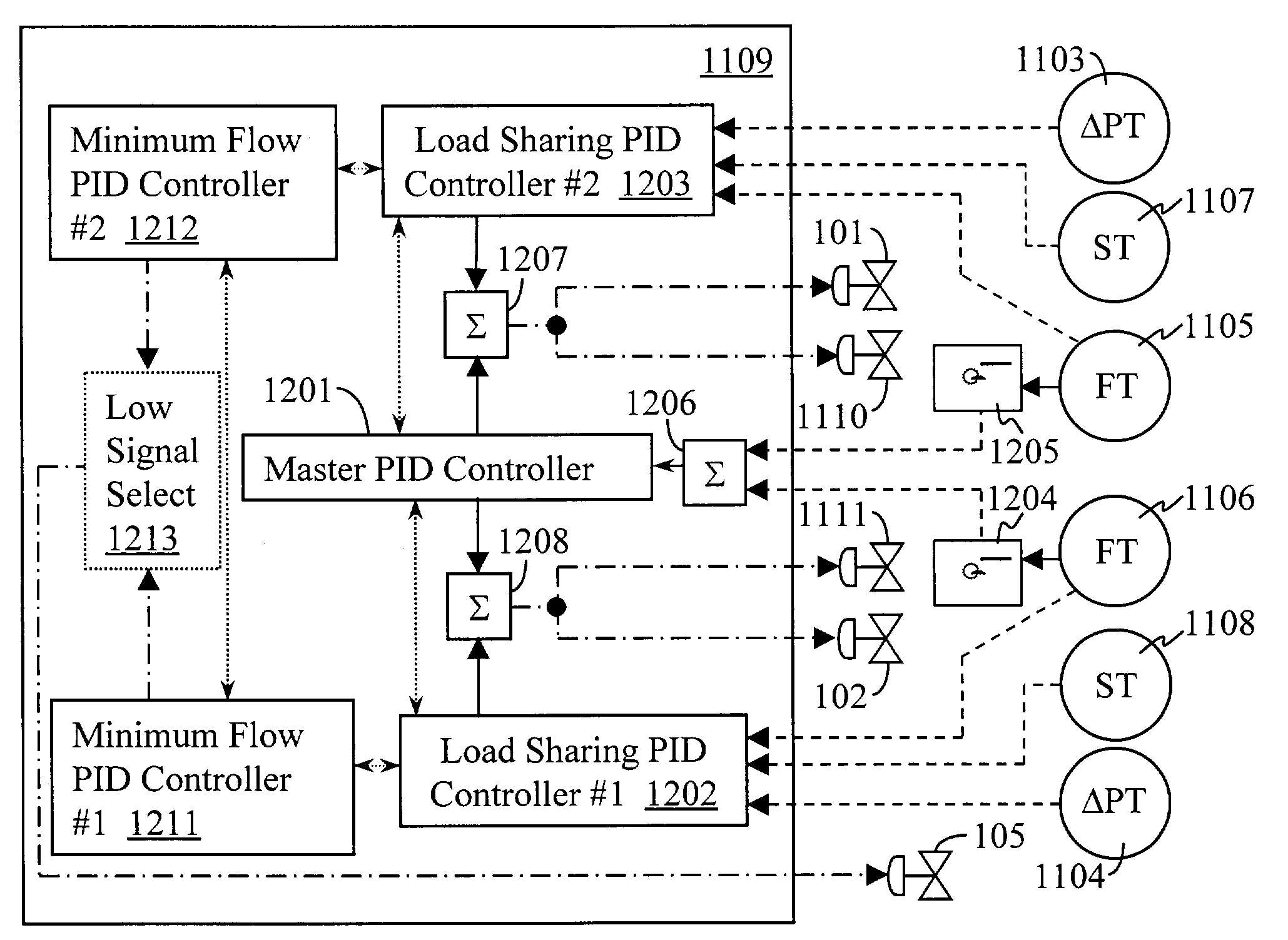
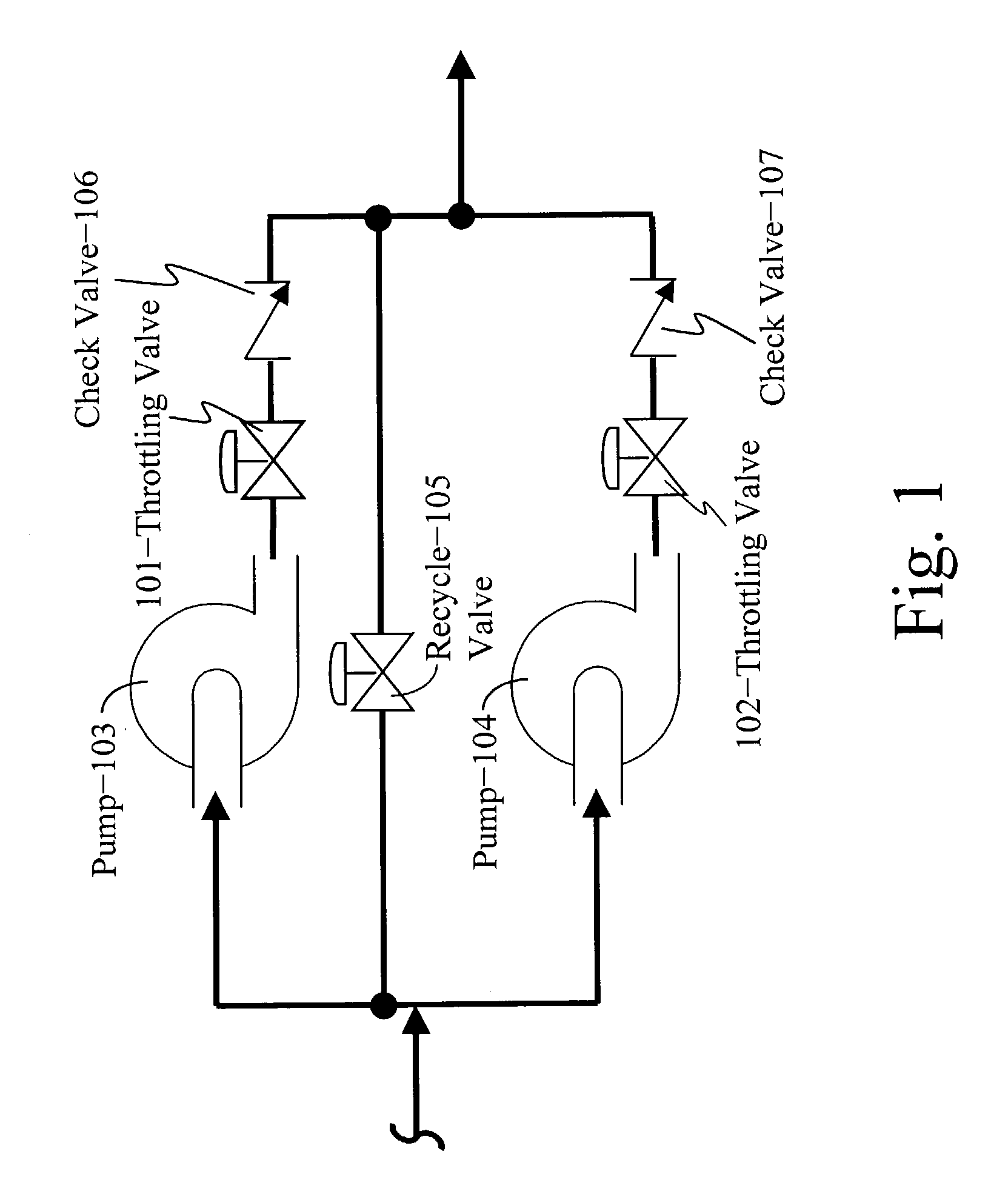
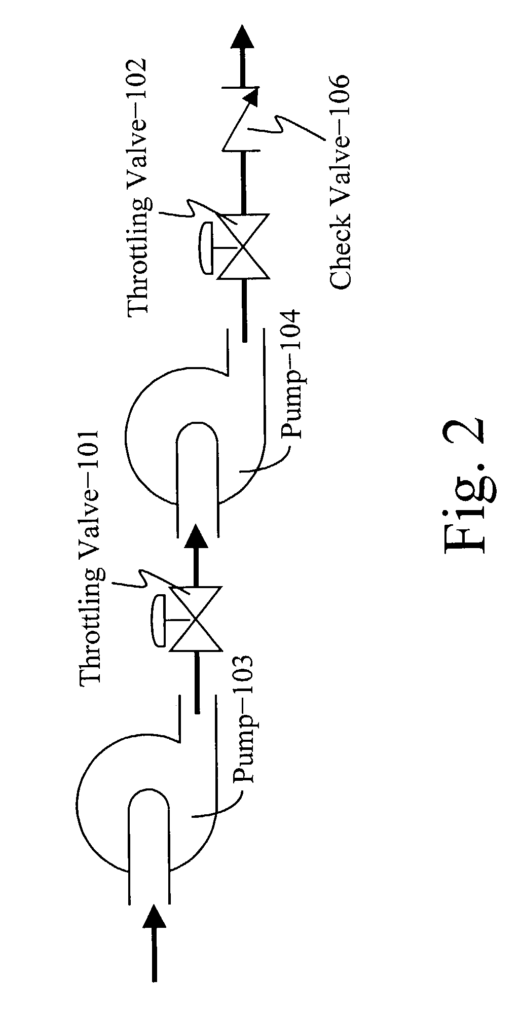
[0027]When operating two or more centrifugal or axial pumps 103, 104 (FIGS. 1 and 2) in a piping network (either in parallel or series), there are infinite combinations of operating points that satisfy the process requirements. To maintain safe and efficient pump operation, while multiple pumps 103, 104 are functioning simultaneously in the same piping network, each pump's operating point must be observed with respect to its minimum flow limit. As mentioned, pumps may be operated in parallel (FIG. 1) or in series (FIG. 2); combinations of parallel and series can be managed similarly.

[0028]Pump performance can be controlled through changes in rotational speed (see FIG. 11: 1107, 1108) or through throttling valves 101, 102 usually in the discharge of a pump, as shown in FIGS. 1, 2 and 11, upstream of the check valves 106, 107. The present invention is also applicable to pumps having variable geometry for controlling their performance.

[0029]FIG. 3 shows a pump performance map where eac...


PUM


Abstract

Often, an application or process calls for multiple pumps operating within a piping network. Pump load, such as flow rate or pressure, is shared between these multiple pumps. The present disclosure relates to effective means of distributing the pumping load in a manner that satisfies the process requirements while keeping the pumping machinery safe from functioning in damaging operating regions. It also discloses a method of operating pumps in an efficient or optimal fashion. An additional aspect is a method of using an open-loop response to deal with large transients threatening to force a pump into an operating region that might result in damage or destruction.

Description

CROSS REFERENCE TO RELATED APPLICATIONS[0001]This application contains disclosure from and claims the benefit under Title 35, United States Code, §119(e) of the following U.S. Provisional Application: U.S. Provisional Application Ser. No. 60 / 390,072 filed Jun. 20, 2002, entitled METHOD AND APPARATUS FOR CONTROLLING MINIMUM CONTINUOUS STABLE FLOW OF A PUMP STATION WITH MULTIPLE DYNAMIC PUMPS.STATEMENT REGARDING FEDERALLY SPONSORED RESEARCH OR DEVELOPMENT[0002]Not applicable.REFERENCE TO MICROFICHE APPENDIX[0003]Not applicable.TECHNICAL FIELD[0004]This invention relates generally to a method and apparatus for automatic control of multiple pumps operated either in parallel (to increase flow rate to and / or from the process) or in series (to increase the overall head). More specifically, the invention relates to a method for manipulating the operation of pumps, thereby preventing them from reaching their minimum flow limit until process requirements are such that all pumps must reach the...

Claims


Application Information

Patent Timeline
IPC IPC(8): G05D11/00F04D15/00F04D15/02
CPCF04D15/029F04D15/0022
Inventor MIRSKY, SAULNARAYANAN, KRISHNAN
Owner COMPRESSOR CONTROLS LLC
Why Eureka
Try Eureka