Parallel handle system and method for designing a parallel handle system

a handle system and handle technology, applied in the direction of wing handles, rigid containers, wing knobs, etc., can solve the problems of workers' disability, discomfort and pain, discomfort and pain, etc., and achieve the effect of avoiding undue pressure on the carpal tunnel zon

Inactive Publication Date: 2006-03-14
TILLIM STEPHEN L
View PDF158 Cites 8 Cited by
  • Summary
  • Abstract
  • Description
  • Claims
  • Application Information

AI Technical Summary

Benefits of technology

[0018]In this regard the present invention provides a handle or apparatus for use with the hand that includes: a radial section having a side for receiving the thumb of the hand and having a side for receiving the index finger of the hand, and the radial section having a surface for engaging a portion of the palmar surface of the hand; a middle section having a side for receiving at least a portion of the middle finger and at least a portion of the ring finger of the hand and having a surface that avoids placing undue pressure on a surface of the hand located over the carpal tunnel; and an ulnar section having a side for receiving the small finger of the hand and having a surface for engaging a portion of the palmar surface of the hand so as to position the end of the small finger.
[0019]Also, the present invention provides a method for designing a handle that corresponds to the sizes of a hand, that includes the steps of: setting the hand in a T position so that the tips of the of the long fingers of the hand are substantially in alignment; measuring the distance across the metacarpal bones of the long fingers of a hand from the radial side to the ulnar side of the palm of the hand thereby defining a width of the handle; and setting the distance from the ulnar palmar line to the distal side of the carpal tunnel zone equal to or less than the distance from the ulnar palmar line to the radial palmar line such that undue pressure on the carpal tunnel zone is avoided.

Problems solved by technology

Discomfort and hand fatigue occurs with repetitive use of handles for tools with hinges based on the lever system.
However, the repetitive use of such tools can result in disability for workers.
The pressure produced in that area of the palm can cause discomfort and pain.
Also such pressure on the TCL can limit the effectiveness and accuracy of a in the measurement of grip strength, such as when the wrist is injured.
However, tools generally based on a triangular levered system typically may not comfortable.

Method used


Image

  • Parallel handle system and method for designing a parallel handle system
  • Parallel handle system and method for designing a parallel handle system
  • Parallel handle system and method for designing a parallel handle system

Examples


Embodiment Construction

[0033]In order to more clearly and concisely describe the subject matter of the present invention, the following definition for the T Position, Spread T Position STP and Closed T Position CTP are intended to provide guidance as to the meanings of specific terms used in the following written description. In addition, it is to be understood that the phraseology or terminology employed herein is for the purpose of description, and not to be construed in a limiting sense. The following discussion relates to areas of the hand in relation to the present invention with reference to FIGS. 1 through 6.

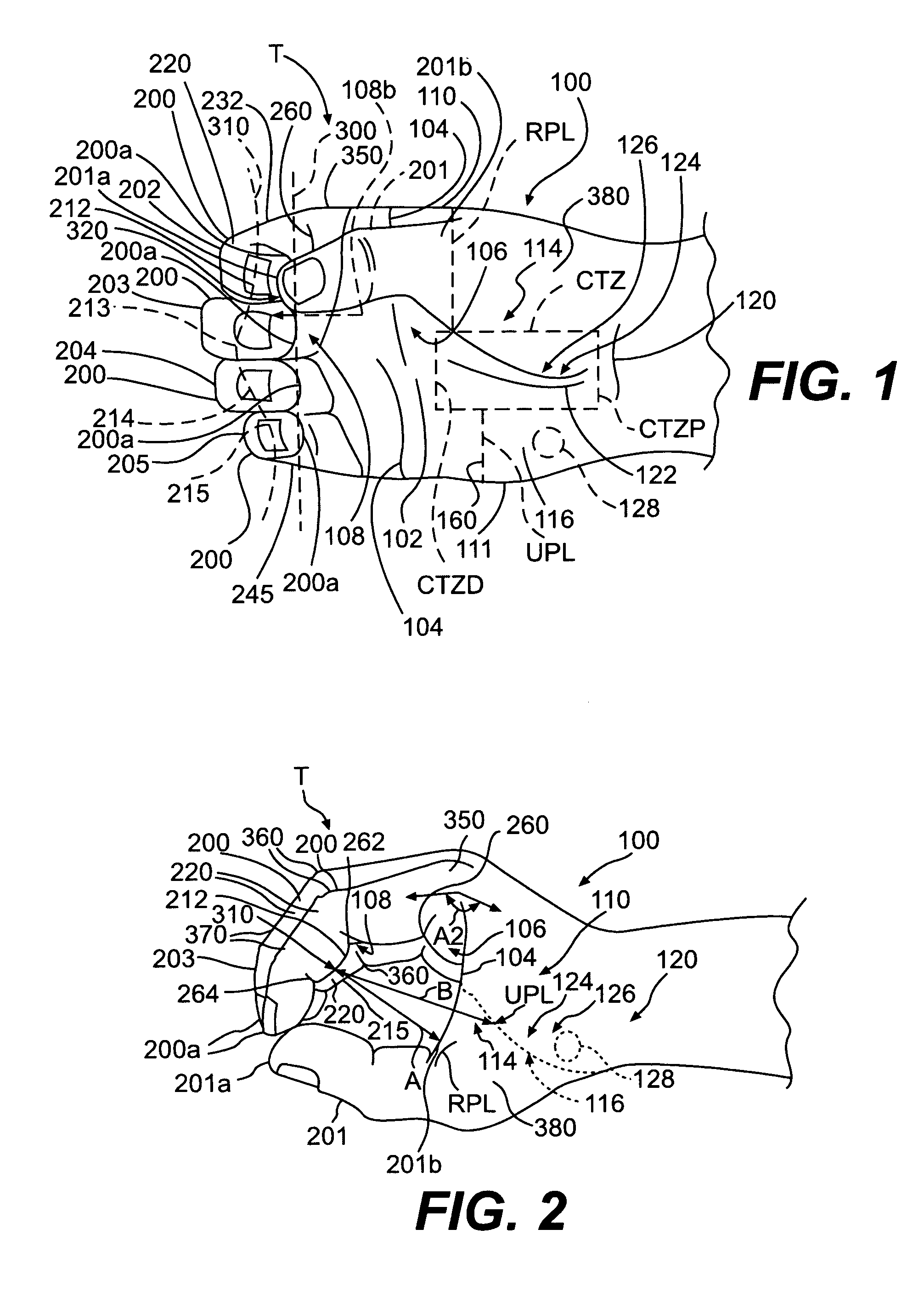
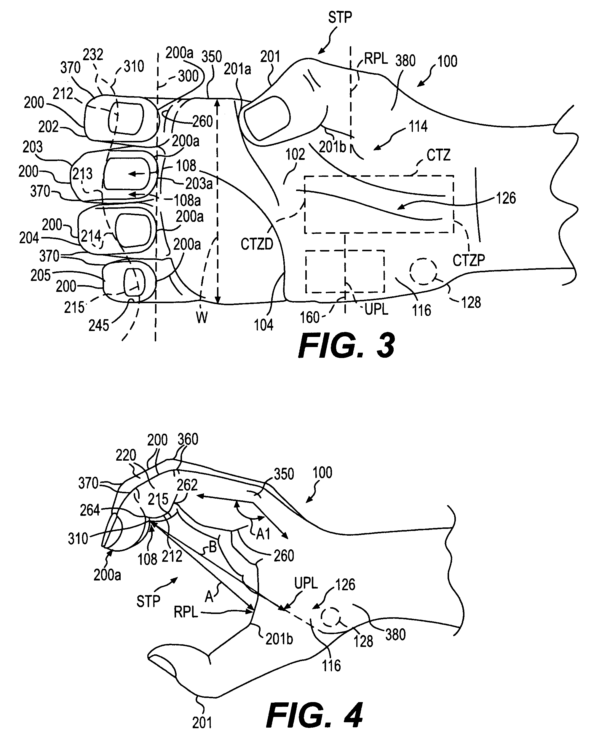
[0034]FIG. 1 is a view of the palm 102 of the hand 100 and FIG. 2 the radial side 110 of hand 100. FIG. 1 and FIG. 2 illustrate the hand 100 to the T Position.

[0035]The T Position is the position the hand 100 assumes when the tips 200a of the long fingers 200 are substantially aligned, line 300,and the tip 201a of the thumb 201 opposes the space 320 between the index finger 202 and middle finge...


PUM


Abstract

A parallel handle, parallel handle system and method for designing parallel handles for a hand for use with tools or control mechanisms, that includes a handle having a radial section having a side for receiving the thumb and having a side for receiving the index finger, the radial section having a surface for engaging a portion of the palmar surface of the hand, a middle section having a side for receiving at least a portion of the middle finger and at least a portion of the ring finger and having a surface that avoids placing undue pressure on a surface of the hand located over the carpal tunnel, and an ulnar section having a side for receiving the small finger and having a surface for engaging a portion of the palmar surface of the hand so as to position the end of the small finger.

Description

CLAIM FOR PRIORITY[0001]This application is a Continuation-in-Part of Non-Provisional Application Ser. No. 10 / 279,111 filed Oct. 24, 2002. Priority is claimed based on U.S. Application Ser. No. 10 / 279,111 and is a continuation-in-part of PCT Application No. PCT / US02 / 33956, both filed Oct. 24, 2002, which claims the priority of the corresponding U.S. Provisional Application No. 60 / 330,527 with the filing date of Oct. 24, 2001.FIELD OF INVENTION[0002]The present invention relates to parallel handles, parallel handle systems and methods for designing a parallel handle system for a hand for use in hold or using tools, such as those that hold, grip, cut and bite objects. The present invention also relates a parallel handle and parallel handle systems for use with control mechanisms for control of various devices and functions.BACKGROUND OF THE INVENTION[0003]Originally, known as pincers and used to handle hot coals, pliers are an ancient invention of hand tools that hold, grip, cut and b...

Claims


Application Information

Patent Timeline
Patent Type & Authority Patents(United States)
IPC IPC(8): B25G1/04A45C13/26A61B17/00A61B17/28A61B17/30A61B17/32A61B17/88A63B59/00B25C5/02B43K23/004B60T7/08G05G1/06
CPCA61B17/00A61B17/1611A61B17/1686A61B17/2909A61B17/30A61B17/3213A63B23/16B25C5/0285B25G1/102B43K23/004B60T7/08G05G1/06G05G1/503A61B17/1606Y10T16/476A61B17/3201A61B17/8875A61B2017/00424A61B2017/0046A61B2017/00477A61B2017/2918A61B2017/2919A61B2017/2925A61B2017/2927A61B2017/2929A61B2017/2931A61B2017/2939A61B2017/32113A61B2019/461A63B21/05A63B59/0014Y10S16/12Y10T16/44A61B2090/061A63B60/06A63B60/08A63B60/10
Inventor TILLIM, STEPHEN L.
Owner TILLIM STEPHEN L
Why Eureka
Try Eureka