Method and apparatus for cooling combustor liner and transition piece of a gas turbine

a technology of which is applied in the direction of mechanical equipment, machines/engines, lighting and heating apparatus, etc., can solve the problems of premature film cooling of the combustor liner and transition piece, large nox emissions, and inability to meet the requirements of prior conventional combustor components

Active Publication Date: 2006-03-14
GENERAL ELECTRIC CO
View PDF28 Cites 227 Cited by
  • Summary
  • Abstract
  • Description
  • Claims
  • Application Information

AI Technical Summary

Benefits of technology

[0045]One advantages of this invention is that it can be applied to existing designs, is relatively inexpensive and easy to fit, and provides a local solution that can be applied to any area on the side panel needing additional cooling.

Problems solved by technology

), the high temperatures of diffusion combustion result in relatively large NOx emissions.
Although lean premixed combustion is cooler than diffusion combustion, the flame temperature is still too hot for prior conventional combustor components to withstand.
Furthermore, because the advanced combustors premix the maximum possible amount of air with the fuel for NOx reduction, little or no cooling air is available, making film-cooling of the combustor liner and transition piece premature at best.
The various known techniques enhance heat transfer but with varying effects on thermal gradients and pressure losses.
A low heat transfer rate from the liner can lead to high liner surface temperatures and ultimately loss of strength.
Several potential failure modes due to the high temperature of the liner include, but are not limited to, cracking of the aft sleeve weld line, bulging and triangulation.
These mechanisms shorten the life of the liner, requiring replacement of the part prematurely.

Method used


Image

  • Method and apparatus for cooling combustor liner and transition piece of a gas turbine
  • Method and apparatus for cooling combustor liner and transition piece of a gas turbine
  • Method and apparatus for cooling combustor liner and transition piece of a gas turbine

Examples


Embodiment Construction

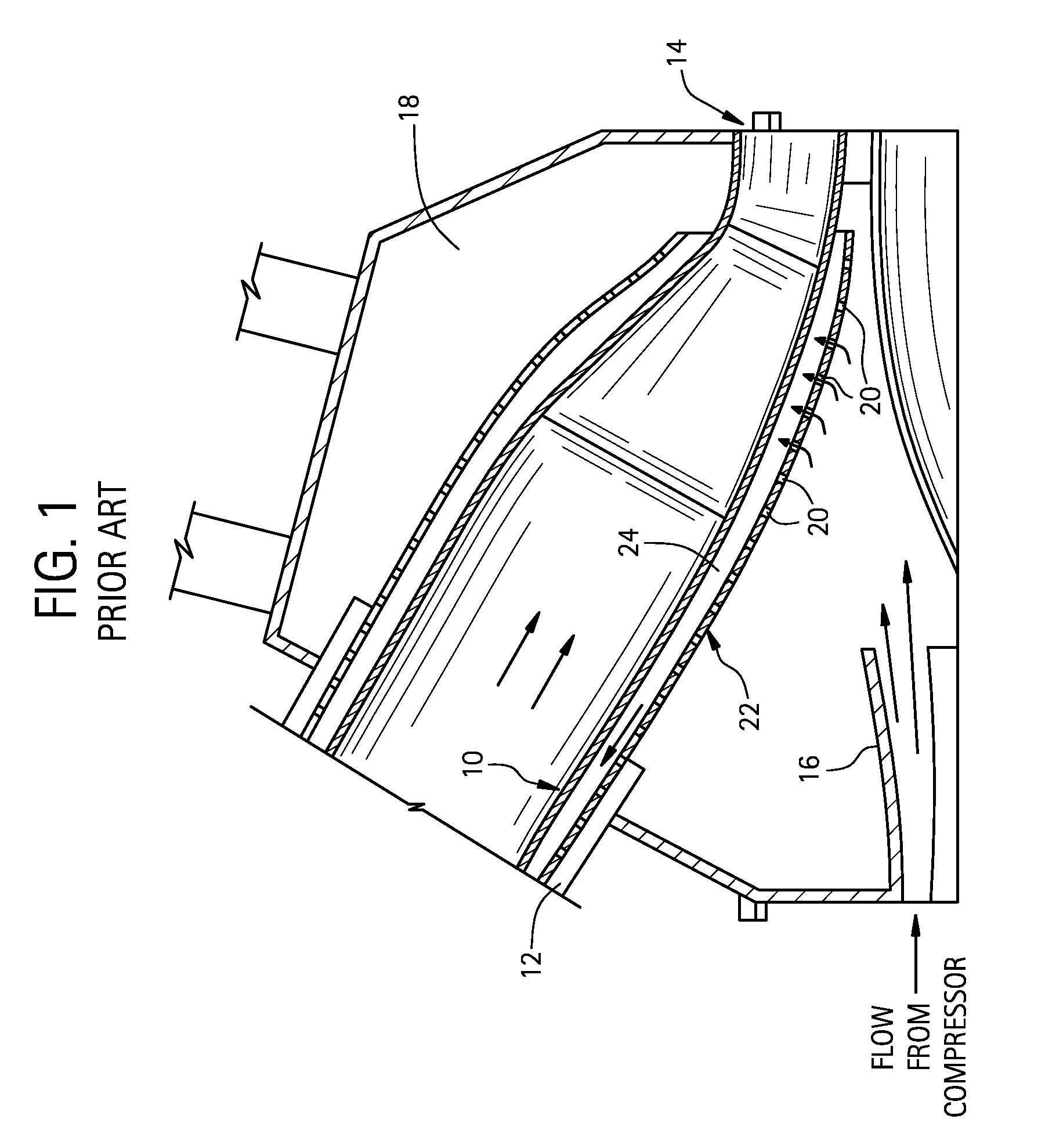
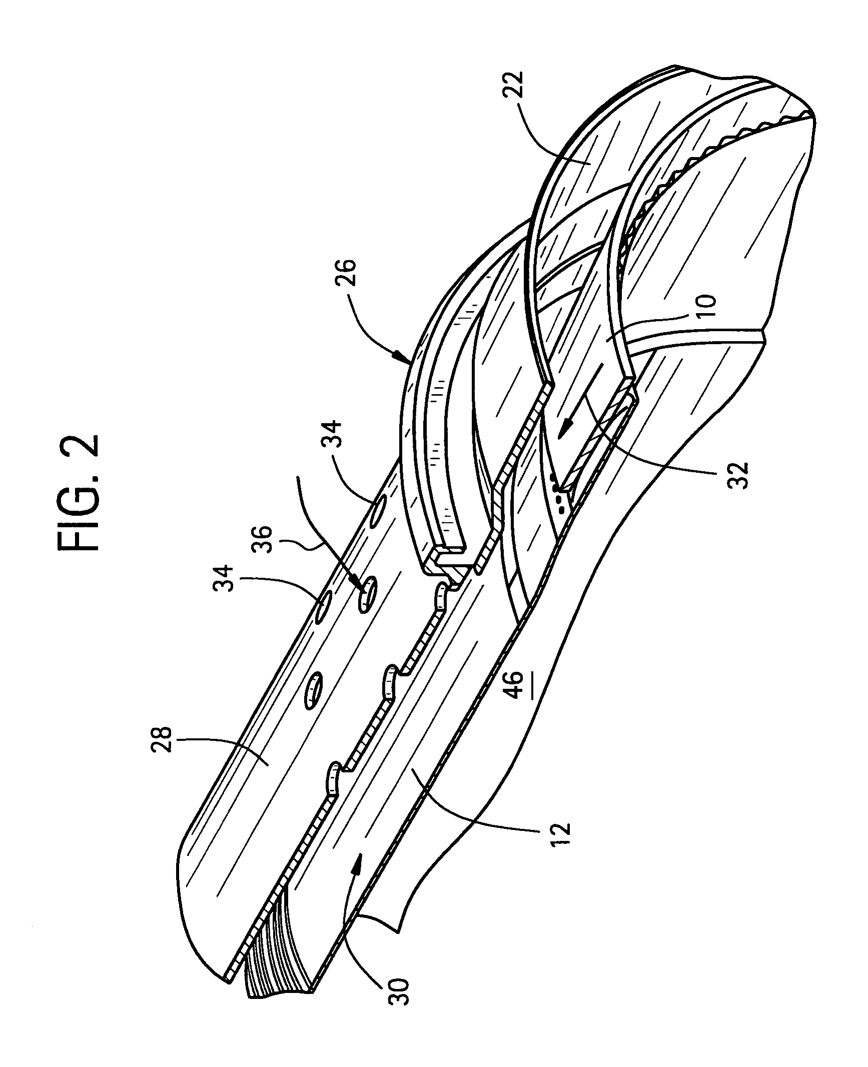
[0024]With reference to FIGS. 1 and 2, a typical gas turbine includes a transition piece 10 by which the hot combustion gases from an upstream combustor as represented by the combustor liner 12 are passed to the first stage of a turbine represented at 14. Flow from the gas turbine compressor exits an axial diffuser 16 and enters into a compressor discharge case 18. About 50% of the compressor discharge air passes through apertures 20 formed along and about a transition piece impingement sleeve 22 for flow in an annular region or annulus 24 (or, second flow annulus) between the transition piece 10 and the radially outer transition piece impingement sleeve 22. The remaining approximately 50% of the compressor discharge flow passes into flow sleeve holes 34 of an upstream combustion liner cooling sleeve (not shown) and into an annulus between the cooling sleeve and the liner and eventually mixes with the air in annulus 24. This combined air eventually mixes with the gas turbine fuel in...


PUM


Abstract

A method and apparatus for cooling a combustor liner and transitions piece of a gas turbine include a combustor liner with a plurality of circular ring turbulators arranged in an array axially along a length defining a length of the combustor liner and located on an outer surface thereof; a first flow sleeve surrounding the combustor liner with a first flow annulus therebetween including a plurality of axial channels (C) extending over a portion of an aft end portion of the liner parallel to each other, the cross-sectional area of each channel either constant or varying along the length of the channel, the first flow sleeve having a plurality of rows of cooling holes formed about a circumference of the first flow sleeve for directing cooling air from the compressor discharge into the first flow annulus; a transition piece connected to the combustor liner and adapted to carry hot combustion gases to a stage of the turbine; a second flow sleeve surrounding the transition piece a second plurality of rows of cooling apertures for directing cooling air into a second flow annulus between the second flow sleeve and the transition piece; wherein the first plurality of cooling holes and second plurality of cooling apertures are each configured with an effective area to distribute less than 50% of compressor discharge air to the first flow sleeve and mix with cooling air from the second flow annulus.

Description

BACKGROUND OF THE INVENTION[0001]This invention relates to internal cooling within a gas turbine engine; and more particularly, to apparatus and method for providing better and more uniform cooling in a transition region between a combustion section and discharge section of the turbine.[0002]Traditional gas turbine combustors use diffusion (i.e., non-premixed) combustion in which fuel and air enter the combustion chamber separately. The process of mixing and burning produces flame temperatures exceeding 3900° F. Since conventional combustors and / or transition pieces having liners are generally capable of withstanding a maximum temperature on the order of only about 1500° F. for about ten thousand hours (10,000 hrs.), steps to protect the combustor and / or transition piece must be taken. This has typically been done by film-cooling which involves introducing relatively cool compressor air into a plenum formed by the combustor liner surrounding the outside of the combustor. In this pri...

Claims


Application Information

Patent Timeline
Patent Type & Authority Patents(United States)
IPC IPC(8): F02C1/00F02G3/00F02C7/12F23R3/06F02C7/18F23R3/00F23R3/30F23R3/42
CPCF23R3/002F23R3/06F23R2900/03044F23R2900/03042
Inventor INTILE, JOHN CHARLESWEST, JAMES A.BYRNE, WILLIAM
Owner GENERAL ELECTRIC CO
Why Eureka
Try Eureka