Changed condition indicator

a condition indicator and indicator technology, applied in the direction of instruments, thermometers using mean/integrated values, heat measurement, etc., can solve the problems of inability to use such an apparatus with every item, inability to accurately indicate the condition of the item, and inability to meet the requirements of use,

Inactive Publication Date: 2006-03-14
THERMOPROX
View PDF33 Cites 14 Cited by
  • Summary
  • Abstract
  • Description
  • Claims
  • Application Information

AI Technical Summary

Benefits of technology

[0020]It is a further object of the present invention to provide an indicator apparatus that creates a brilliant color upon an appropriate temperature transition.
[0021]The above list of objects of the present invention is exemplary in nature. Additional features and advantages may be apparent to those skilled in the relevant arts. Furthermore, not every one of the listed objectives may be met in every embodiment of the present invention. The apparatus of the present ...

Problems solved by technology

For example, some vaccines are known to not function properly if stored above a certain temperature.
However, the use of such apparatus with every item in a frozen foo...

Method used


Image

  • Changed condition indicator
  • Changed condition indicator
  • Changed condition indicator

Examples


Embodiment Construction

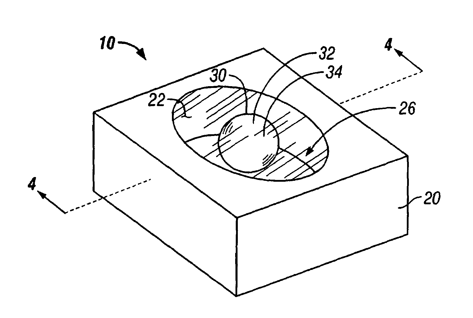
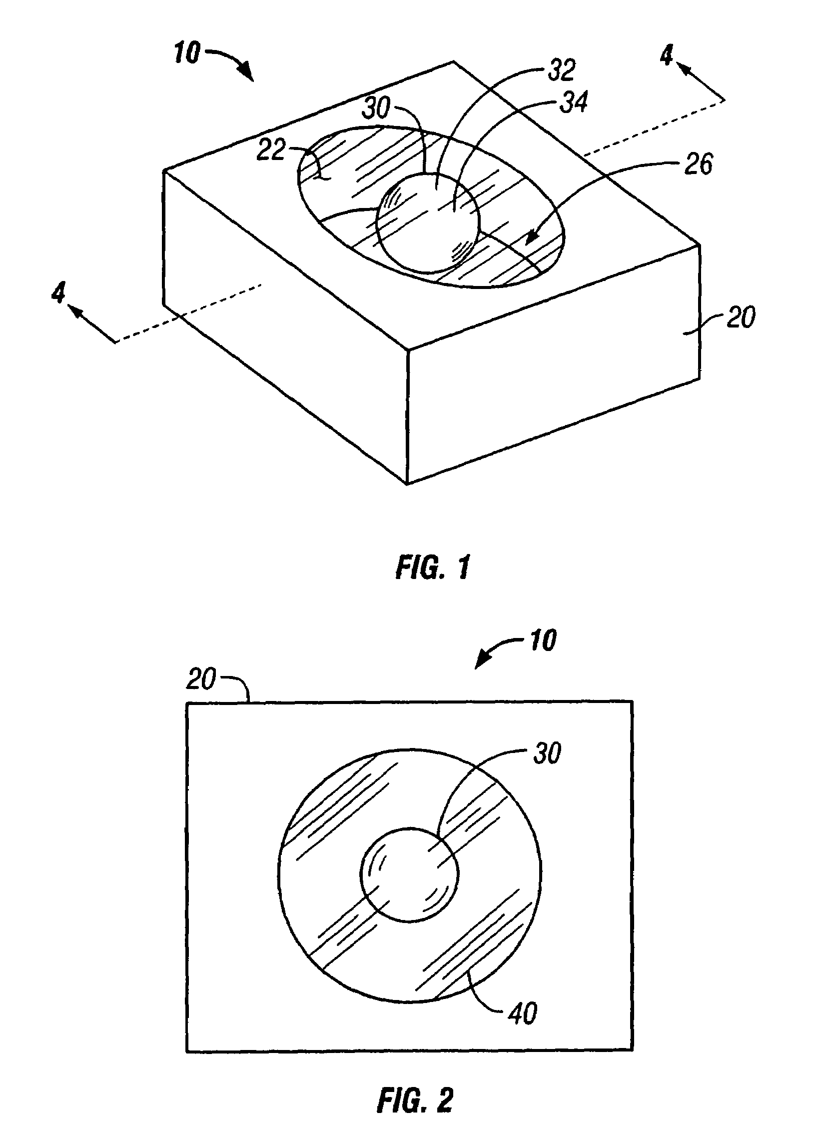
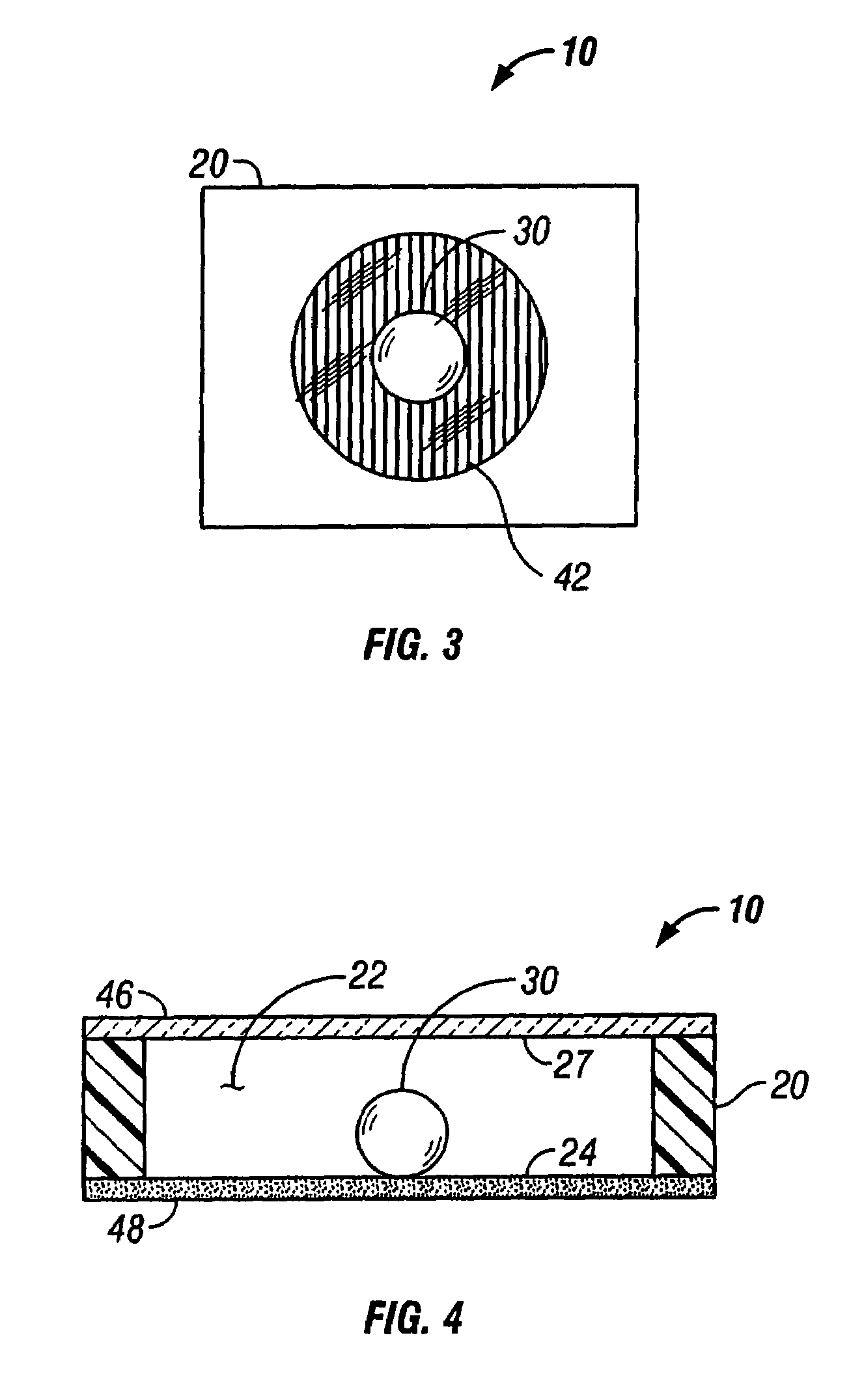
[0036]FIG. 1 is a perspective view of a preferred embodiment of the indicator of the present invention. For exemplary purposes only, the embodiment of a freeze-thaw indicator will be discussed; however, other embodiments are equally available for use. The device 10 comprises a housing 20 and a capsule 30. Housing 20 defines an interior 22. Interior 22 is bounded by a first surface 24 and a second surface 27 (see FIG. 4). A first reactant 26 is provided within housing 20. Reactant 26 may be located within housing 20 in various ways. For example, reactant 26 can be applied directly to surface 24 or reactant 26 may be applied to a piece of material, such as filter paper, and the material placed inside housing 20. In addition to filter paper, other carriers may also be used with the present invention.

[0037]Capsule 30 is located within housing 20. Capsule 30 contains a second reactant 32. Capsule 30 also contains a liquid 34. Liquid 34 is chosen such that it expands upon freezing. A pref...


PUM


Abstract

A device and method of making a device for indicating a change in condition is disclosed. A first embodiment is a device for indicating a transition from a frozen condition to a thawed condition is disclosed. The device includes a housing and a capsule. A first reactant and a liquid are included within the capsule. The liquid is chosen such that it expands upon freezing. The capsule is sized such that when the liquid freezes and expands, the capsule fractures. A second reactant is provided within the housing. The location of the second reactant and the method of attaching (if any) the second reactant to the housing may take various forms. When the liquid within the capsule freezes, it expands and fractures the capsule. Upon thawing, the reactant within the capsule escapes and mixes with the reactant located outside the capsule. A second embodiment is a time-temperature indicator. A flexible housing is used, allowing the user to manually deform the housing to fracture a capsule enclosed therein. The reactants combine to produce a color. The color is chosen to be a different color than the housing, allowing a person viewing the indicator device to quickly and easily determine the status of the object being monitored. The threshold temperature at which the device will indicate a changed condition may be varied. Exemplary temperatures include below the freezing temperature, at the freezing temperature, and above the freezing temperature. The capsule composition may be varied such that it melts at a predetermined temperature. Thus, the device may also be used to indicated whether a high temperature has been met or exceeded.

Description

CROSS-REFERENCE TO RELATED APPLICATIONS[0001]This application is a Continuation-in-Part of U.S. patent application Ser. No. 09 / 925,538 filed on Aug. 10, 2001, now U.S. Pat. No. 6,694,913, which is incorporated herein by reference in its entirety.BACKGROUND OF THE INVENTION[0002]1. Field of the Invention[0003]This invention relates to an indicating apparatus and method of manufacture. More particularly, this invention relates to devices for indicating a change in condition by producing a color change and methods of manufacture therefor.[0004]2. Description of the Related Art[0005]In the preparation and storage of foodstuffs, both raw and cooked, it is desirable to have some manner of indicating whether frozen items have previously been thawed. This is true in both home and commercial (such as a grocery store, supermarket, or restaurant) settings. Such information is useful from health, safety, and nutritional standpoints.[0006]In the healthcare industry, it is well known that some va...

Claims


Application Information

Patent Timeline
IPC IPC(8): G01K1/02G01K3/04G01K11/06
CPCG01K11/06G01K3/04
Inventor COOPERMAN, ISADORE
Owner THERMOPROX
Why Eureka
Try Eureka