
Image projector lamp door with screw tuning component

a technology of image projector and screw tuning, which is applied in the direction of projectors, camera body details, instruments, etc., can solve the problems of inability to replace lamps, inability to use lamps, etc., and achieve the effect of reliable tightening or loosening

Inactive Publication Date: 2006-03-14
FUNAI ELECTRIC CO LTD
View PDF8 Cites 12 Cited by
  • Summary
  • Abstract
  • Description
  • Claims
  • Application Information

AI Technical Summary

Benefits of technology

[0012]The present invention was developed in order to overcome the above-mentioned drawback, and an object thereof is to provide an image projector in which the lamp box can be replaced without the need for a screw-turning tool.
[0015]In the present invention, adopting a configuration in which a rib extends in a straight line makes it easy for the leading end of the rib to be locked in the head portion of the lamp box fixing screw, and to tighten or loosen the lamp box fixing screw.
[0016]Also, if a reinforcing component is provided to the base end of the rib, the lamp box fixing screw can be reliably tightened or loosened when this lamp box fixing screw is tightened or loosened.

Problems solved by technology

During use of the image projector, the lamp sometimes becomes unusable due to deterioration or reaching the end of its service life and must be replaced unexpectedly.
Consequently, when the lamp becomes unusable due to deterioration or reaching the end of its service life, if a screw-turning tool cannot be provided, the lamp cannot be replaced, which creates a situation in which the image projector cannot be used.
Also, even if the measures disclosed in the patent references described above are put in place, the above-mentioned drawback cannot be overcome.
By this means, even when the lamp must be replaced unexpectedly, a situation does not arise in which the lamp cannot be replaced and the image cannot be displayed due to the inability to provide a screw-turning tool.

Method used


Image

  • Image projector lamp door with screw tuning component
  • Image projector lamp door with screw tuning component
  • Image projector lamp door with screw tuning component

Examples


Embodiment Construction

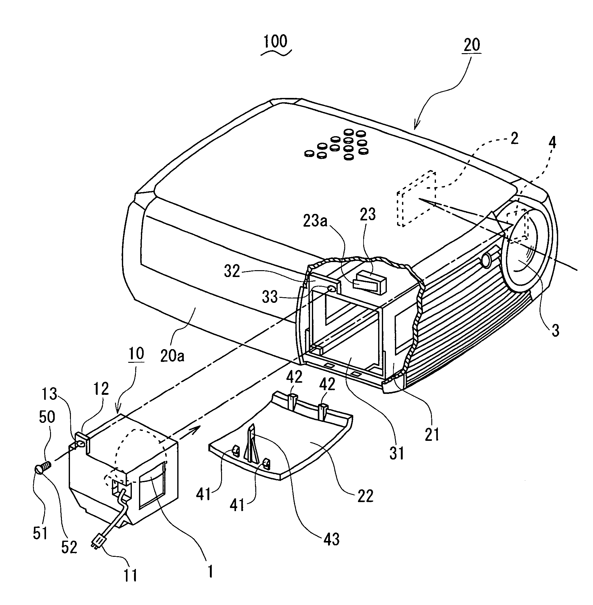
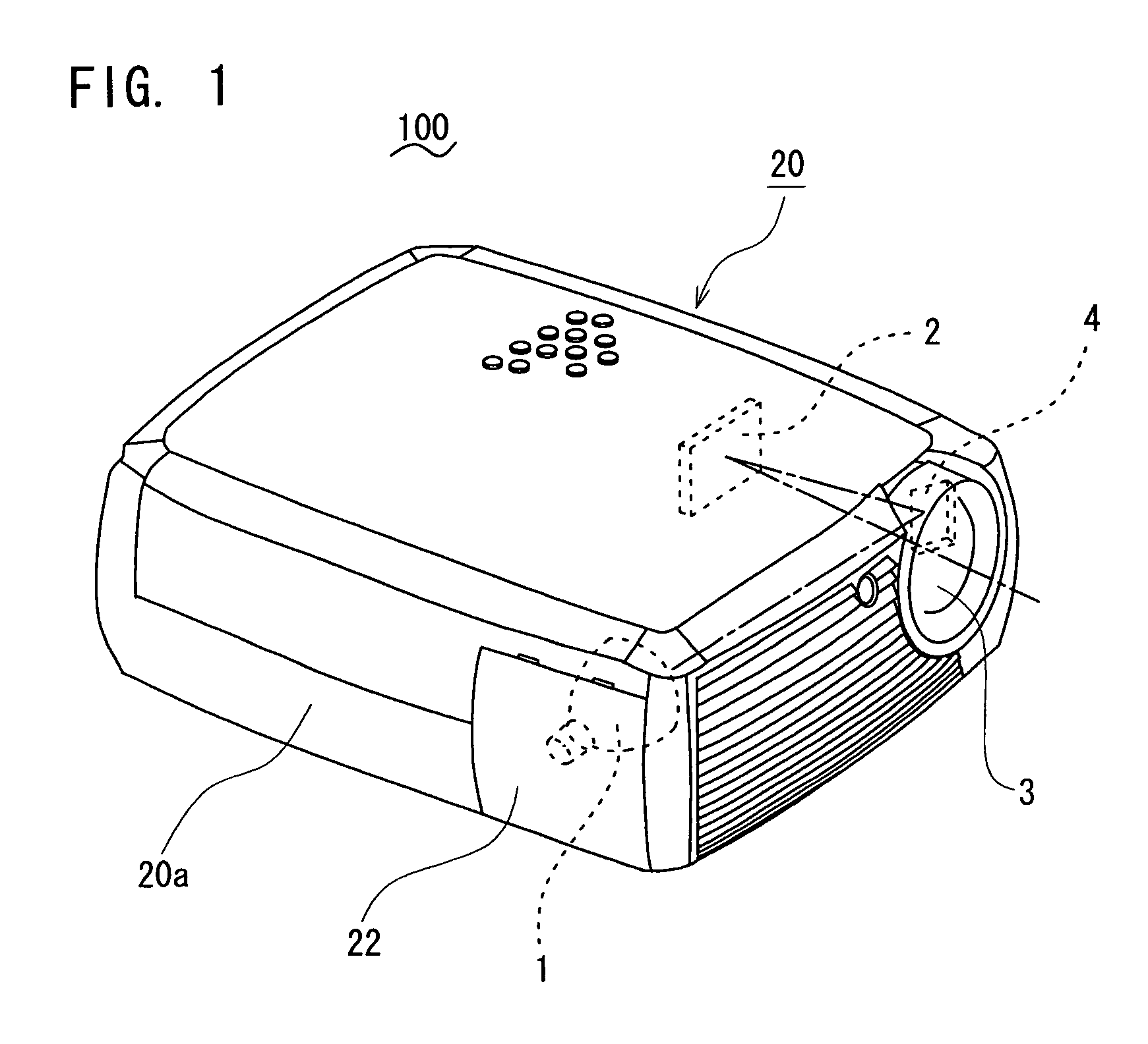
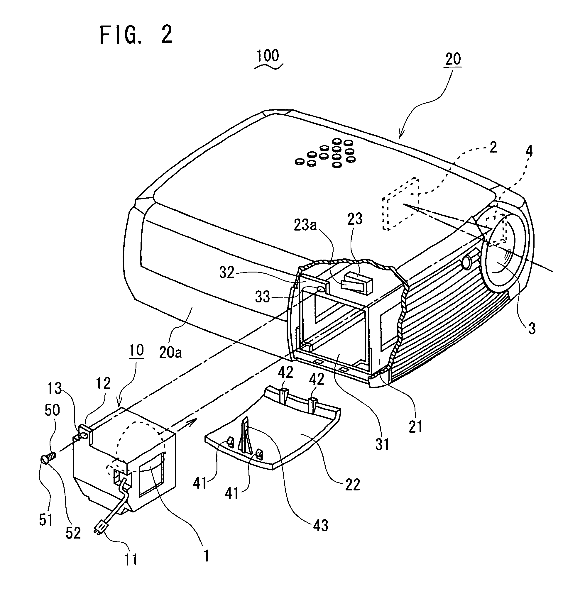
[0023]A specific embodiment will be described hereinafter with reference to the drawings. In FIGS. 1 and 2, an image projector 100 comprises a device whereby an image is formed by an image forming element 2 using light used for image projection emitted from a lamp 1, based on an image signal inputted from a personal computer, video camera, or the like; and the image is projected and displayed from a projection lens 3 onto a screen, wall surface, or the like. The device is configured such that a lamp box 10 that contains the lamp 1 can be inserted into the case (hereinafter referred to as “the case”) 20.

[0024]The lamp box 10 contains the lamp 1 and is provided with a connector 11 and a screw-inserting component 12. The connector 11 is designed to supply electrical power to the lamp 1. The screw-inserting component 12 is designed to threadably secure the lamp box 10 inside the case 20, is disposed in the rear panel of the lamp box 10 so as to protrude upward, and has a screw hole 13.

[...


PUM


Abstract

An image projector includes a lamp box containing a lamp, a case for forming a housing for the projector and having an opening for inserting the lamp box into the housing, a lamp housing provided inside the case and used for fixing the lamp box, and a lamp door removably attached to the case and used for opening and closing the opening. The lamp door has a screw-turning component capable of engaging with a groove on the head of the fixing screw when removed from the case, and threadable tightening / loosening can be performed by rotating the lamp door with the screw-turning component engaged with the groove in the fixing screw. This allows the lamp box to be replaced without the need for a screw-turning tool.

Description

BACKGROUND OF THE INVENTION[0001]1. Field of the Invention[0002]The present invention relates to an image projector for projecting an image and displaying it on a screen or the like.[0003]2. Description of the Related Art[0004]There have been known image projectors for using light emitted from a lamp to form an image by means of an image-forming element on the basis of image data from a personal computer, video camera, or the like, and projecting and displaying that image on a screen or the like. This type of image projector has a structure whereby a lamp box containing a lamp can be placed in a case equipped with an image-forming element, and the lamp can be replaced when it becomes unusable due to deterioration or reaching the end of its service life. The lamp is replaced along with the lamp box by removing the lamp box that contains the unusable lamp from the case (case) and installing a lamp box that contains a usable lamp in the case.[0005]In this type of image projector, the l...

Claims


Application Information

Patent Timeline
Patent Type & Authority Patents(United States)
IPC IPC(8): G03B17/00G03B21/00G03B21/20G03B21/22G03B21/14
CPCG03B21/14G03B21/145
Inventor KYOTO, TOMOAKITAKEMI, KAZUTOSHI
Owner FUNAI ELECTRIC CO LTD
Learn More