Self-cleaning fluid dispenser

a dispenser and self-cleaning technology, applied in the field of fluid dispensers, can solve the problems of contaminating the solvent, particularly problematic, and the precursors of foam and the resultant foam to have a somewhat adhesive property, and achieve the effect of greatly prolonging the effective service life of the dispenser

Inactive Publication Date: 2006-03-21
SEALED AIR U S
View PDF28 Cites 11 Cited by
  • Summary
  • Abstract
  • Description
  • Claims
  • Application Information

AI Technical Summary

Benefits of technology

[0020]By employing a cleaning fluid comprising both a solvent and a gas and directing such fluid radially outwards from the central bore of the valving rod and against the interior surface of the dispenser, including the interior surface of the discharge port, the dispenser provides an improved means for cleaning those areas of the dispenser that are most prone to foam build-up and occlusion. In this manner, the effective service life of the dispenser is greatly extended.

Problems solved by technology

One difficulty with the foamable compositions used to make polyurethane foam for foam-in-place packaging is that the foam precursors and resultant foam tend to have somewhat adhesive properties.
This tendency is particularly problematic inside of the dispenser from which the foam precursors are ejected.
As the dispenser operates over and over again, particularly in automated or successive fashion, foamable composition tends to build up in the internal mixing chamber and around the discharge port of the dispenser, harden into foam, and block the proper exiting of further foamable composition.
However, the foam precursors and reaction products thereof gradually contaminate the solvent in the reservoir as they are transferred thereto from the valving rod.
Further, while previous techniques for supplying solvent to the discharge end of the dispenser have been somewhat effective, none has been able to deliver solvent directly against the internal surfaces of the mixing chamber and discharge port.

Method used


Image

  • Self-cleaning fluid dispenser
  • Self-cleaning fluid dispenser
  • Self-cleaning fluid dispenser

Examples


Embodiment Construction

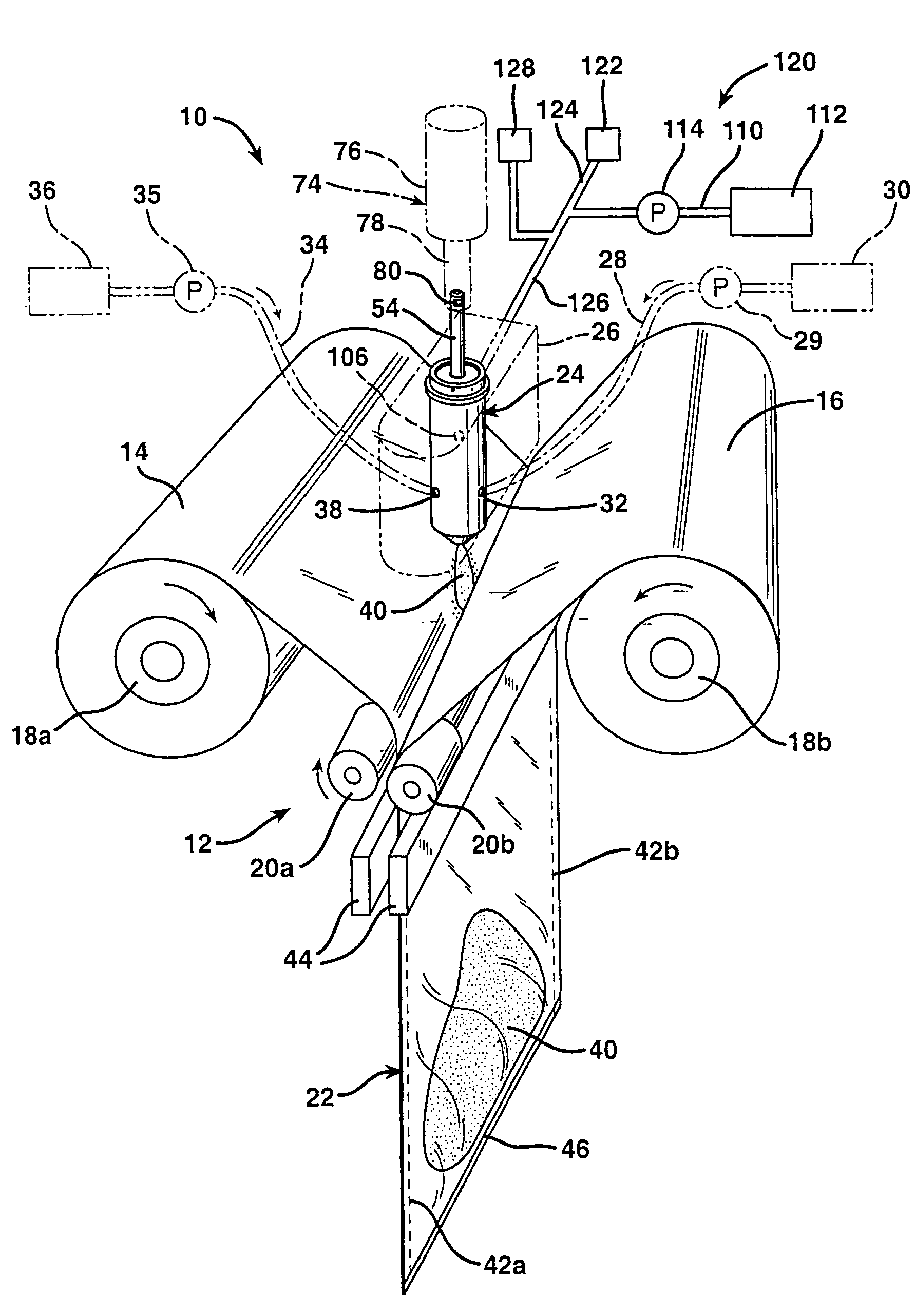
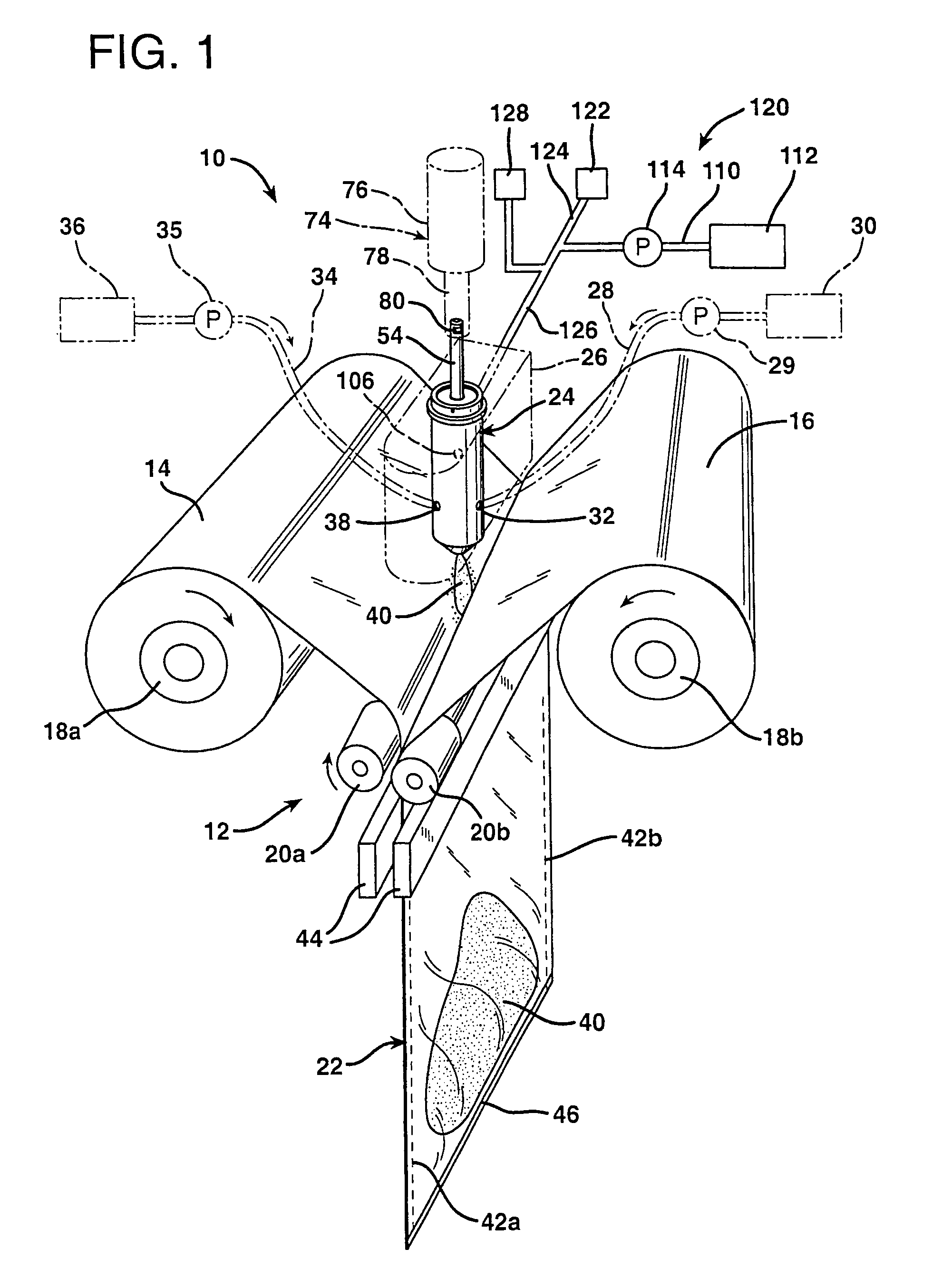
[0052]FIG. 1 shows an apparatus 10 in accordance with the present invention for dispensing fluid into flexible containers and enclosing the fluid within the containers. Apparatus 10 comprises a mechanism generally indicated at 12 that conveys a web of film, or in this case two webs of film 14 and 16, along a predetermined path of travel. Conveying mechanism 12 may include a pair of storage rollers 18a and 18b and a pair of nip rollers 20a and 20b. Film webs 14 and 16 are preferably supplied as wound rolls of film that may be supported on and unwound from respective storage rollers 18a, b. Nip rollers 20a, b rotate in opposing directions such that, when the films webs 14, 16 are passed therebetween, the rotation of the nip rollers cause the film webs to advance from storage rollers 18a, b. The nip rollers 20a, b are made to rotate in this manner by being mechanically or otherwise coupled to a suitable power source (not shown), e.g., an electric motor.

[0053]Film webs 14, 16 may compri...


PUM

PropertyMeasurementUnit
pressureaaaaaaaaaa
pressureaaaaaaaaaa
pressureaaaaaaaaaa

Abstract

A fluid dispenser generally includes a housing and a valving rod disposed in and movable within the housing, the valving rod including a central bore, at least one inlet for receiving a cleaning fluid composed of a solvent and a gas, and one or more outlet ports in fluid communication with the bore, wherein the outlet ports are capable of directing cleaning fluid radially outwards from the bore and against an interior surface of the dispenser to facilitate the removal of at least a portion of any fluid product or derivatives thereof that may be in adherence with such interior surface.

Description

[0001]This application is a division of application Ser. No. 10 / 373,367, filed Feb. 24, 2003, now U.S. Pat. No. 6,811.059.BACKGROUND OF THE INVENTION[0002]The present invention pertains generally to fluid dispensers and related apparatus used to produce on-demand foam-in-place packaging cushions and, more particularly, to an improved system for producing and delivering a cleaning fluid to certain internal portions of such fluid dispensers that are particularly susceptible to occlusion due to build-up and / or hardening of fluid within the dispenser.[0003]The invention finds particularly utility in the field of foam-in-place packaging, which is a highly useful technique for on-demand protection of packaged objects. In its most basic form, foam-in-place packaging comprises injecting foamable compositions from a dispenser into a container that holds an object to be cushioned. Typically, the object is wrapped in plastic to keep it from direct contact with the rising (expanding) foam. As t...

Claims


Application Information

Patent Timeline
Patent Type & Authority Patents(United States)
IPC IPC(8): B65B9/02B65B65/00B05B7/04B05B15/02B29B7/76B29C44/18B29C44/36B65B39/00
CPCB05B7/0408B05B15/025B05B15/0266B29B7/7684B29C44/367B31D5/0078B29C44/182B65B2210/08B31D2205/0023B05B15/55B05B15/557B29B7/7663B29B7/7404B29B7/807
Inventor PIUCCI, JR., VINCENT A.SPERRY, CHARLES R.SADAKIERSKI, WALTER C.SCOTT, SUZANNE M.
Owner SEALED AIR U S
Why Eureka
Try Eureka