Resinous connector

a technology of resinous connectors and connectors, applied in the direction of hose connections, non-disconnectible pipe joints, branching pipes, etc., can solve the problems of insufficient sealing properties, insufficient strength such as shock resistance, and polyamide resins, and achieve the effect of high sealing properties

Active Publication Date: 2006-03-21
TOYODA GOSEI CO LTD
View PDF12 Cites 57 Cited by
  • Summary
  • Abstract
  • Description
  • Claims
  • Application Information

AI Technical Summary

Benefits of technology

[0010]The present invention has been developed in view of the aforementioned circumstances. It is therefore an object of the present invention to let resinous component parts demonstrate higher sealing property by means of an O-ring and to simultaneously inhibit O-rings from being twisted or bruised. It is a further object of the present invention to let resinous component parts keep the load for pulling out hoses from lowering. It is a furthermore object of the present invention to inhibit the nipple of resinous component parts from breaking.
[0026]Thus, in accordance with the present resinous connector, the O-ring is installed in the O-ring groove which is formed in a surface adjacent to the root of the nipple or in the surface of the root. Therefore, when press-in fitting the nipple of the present resinous connector into hoses, the O-ring does not contact with hoses from the initial press-in fitting period to the intermediate press-in fitting period at all, but is rubbed therewith in the final press-in fitting period only. Accordingly, it is possible to inhibit the O-ring from being twisted or bruised because the time period during which the O-ring is rubbed is diminished. Consequently, the present resinous connector can demonstrate a higher sealing property. Moreover, when the O-ring groove is formed at the root of the nipple, it is possible to reduce the overall length of the nipple, because a surface of the O-ring groove can be disposed continuously from a surface of the sealing projection disposed in most proximity to the base.
[0027]Further, when the root of the nipple comprises the outer periphery being formed of the first resin and the inner periphery being formed of the second resin, it is possible to inhibit the root from breaking because the first resin of high toughness is employed. Furthermore, even if the inner periphery being formed of the second resin should have broken, it is possible to avoid such a drawbacks that fuels leak through the nipple, because the first resin keeps covering the root at the outer periphery.
[0028]Moreover, when the base comprises the outer periphery being formed of the first resin and the inner periphery being formed of the second resin, the present resinous connector can demonstrate a higher gas-barrier property while being weldable to the container such as fuel tanks.
[0029]In addition, when the O-ring groove of the nipple is constructed to comprise a bottom,being covered with the first resin, the first resin upgrades the sealing property between the present resinous connector and hoses by way of the O-ring.

Problems solved by technology

However, polyamide resins have a disadvantage in that they might be insufficient in terms of strengths such as shock resistance.
However, when the regulation pertaining the fuel permeation is strict, resinous component parts whose nipple is formed of polyamide resins might be insufficient in terms of the sealing property when the connector is simply fitted into hoses by press-in fitting.
Accordingly, O-rings might be twisted or bruised.
Consequently, various countermeasures have been devised, for example, reducing the thickness of O-rings, or forming the cross-section of O-rings anomalously, If such is the case, however, no further improvement of the sealing property can be expected because the tightening allowance of O-rings has become smaller.
Thus, the problem of increased cost has arisen because no standard O-rings can be applied to resinous component parts.
Moreover, the connector composed of polyamide resins exhibits low shock resistance.
Accordingly, in resinous component parts whose nipple projects perpendicularly to the surface of fuel tanks, a problem occurs in that there are many limitations in designing the resinous component parts, because stresses concentrate at the root of the nipple so much that the nipple might break at the root.
In this instance, however, a problem arises in that the load for pulling out hoses has lowered gradually because the cover layer composed of polyethylene resins is fatigued by stresses.

Method used


Image

  • Resinous connector
  • Resinous connector
  • Resinous connector

Examples


examples

[0043]The present invention will be hereinafter described in more detail with reference to specific examples. Note that the present invention is applied to a connector for cut-off valves which are fastened to automobile fuel tanks, or a connector for breather tubes, in the present examples.

example no.1

Example No. 1

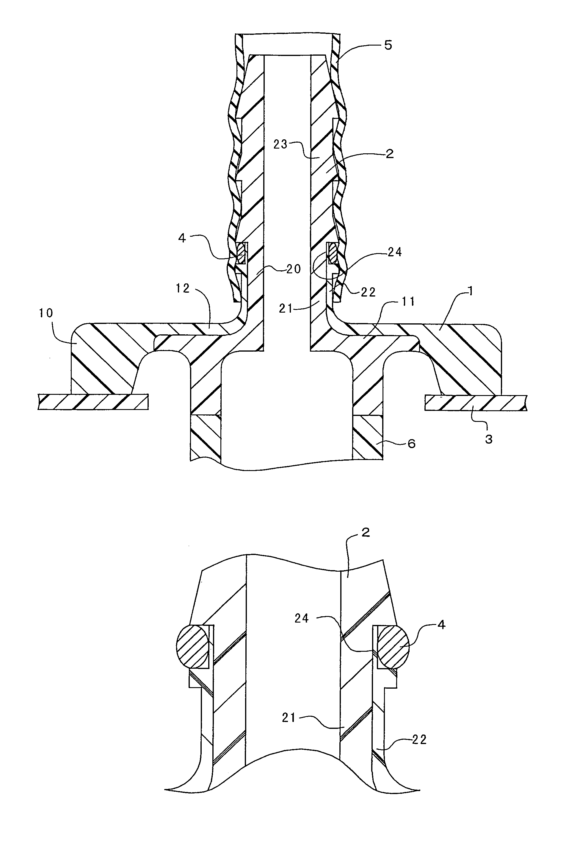
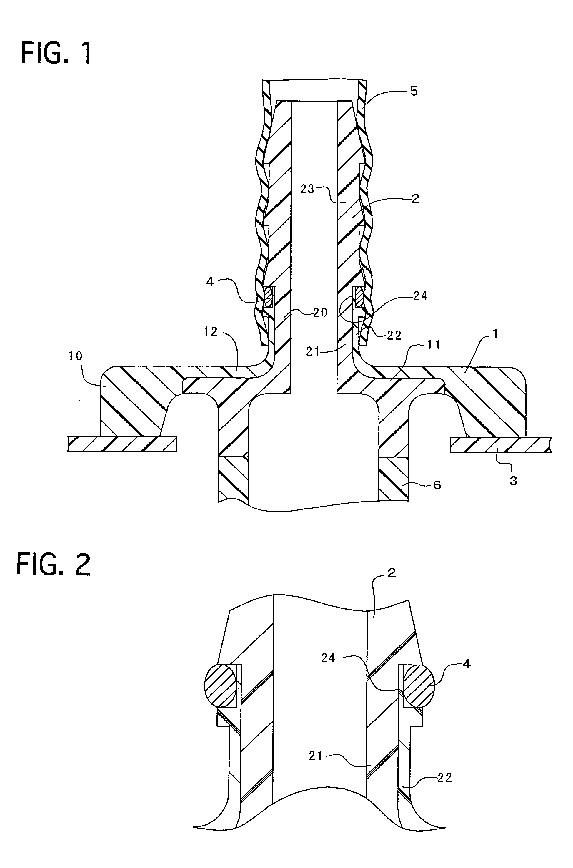
[0044]FIG. 1 illustrates a resinous connector according to Example No. 1 of the present invention, which is fastened to a fuel tank 3, which is equipped with an O-ring 4, and which is fitted into a hose 5 by press-in fitting, as the cross-sectional view. FIG. 2 illustrates an enlarged cross-sectional view when the resinous connector according to Example No. 1 is equipped with the O-ring 4.

[0045]The resinous connector comprises a flange-shaped base 1, and a fur tree-shaped nipple 2 which projects from the base 1. An outer periphery 10 of the base 1 is formed of an acid-modified polyethylene resin alone. Further, an inner periphery of the base 1 comprises a base inner layer 11 being formed of a polyamide resin, and a base outer layer 12 being formed of the acid-modified polyethylene resin. Furthermore, the base inner layer 11 is formed as a cylinder shape, and is fastened by welding to a functional component part 6 such as the housing of cut-off valves. Moreover, a root 2...


PUM

PropertyMeasurementUnit
distanceaaaaaaaaaa
lengthaaaaaaaaaa
lengthaaaaaaaaaa

Abstract

A resinous connector includes a flange-shaped base, a nipple, an O-ring, and an O-ring groove. The nipple extends from the base, and has an outer peripheral surface and sealing projections disposed on the outer peripheral surface. The sealing projections have a substantially triangle-shaped cross section whose diameter reduces in the direction away from the base. The O-ring is disposed between the nipple and a hose. The O-ring groove is formed at a root of the nipple in the outer peripheral surface, and is disposed at a position closer to the base than the sealing projection disposed in most proximity to the base. The resinous connector can inhibit the O-ring from being twisted or bruised by the hose.

Description

BACKGROUND OF THE INVENTION[0001]1. Field of the Invention[0002]The present invention relates to a resinous connector which is welded to resinous containers having an opening so as to cover the opening, and whose leading end is fitted into a hose by press-in fitting and is fastened thereto. A resinous connector according to the present invention can be used as connectors for cut-off valves which are disposed in resinous fuel tanks, and as connectors for breather tubes.[0003]2. Description of the Related Art[0004]Fuel tanks boarded on automobiles have been more and more made of resin in view the lightweight requirement. Fuel tanks are required to prohibit fuels from permeating. Accordingly, it is necessary to use resinous materials, whose gas-barrier property is good, for making fuel tanks. As a resin whose gas-barrier property is appropriate for the application, polyamide resins have been known. However, polyamide resins have a disadvantage in that they might be insufficient in term...

Claims


Application Information

Patent Timeline
Patent Type & Authority Patents(United States)
IPC IPC(8): F16L3/04B60K15/03F16L33/30
CPCF16L33/30
Inventor KANEKO, KENICHIRO
Owner TOYODA GOSEI CO LTD
Why Eureka
Try Eureka