
Golf club head

a golf club and head technology, applied in the field of golf club heads, can solve the problems of slow movement of the putter head before striking the ball, it is not easy for the golfer to strike the ball, and the putter head is usually not exerted with sufficient force, so as to facilitate the adjustment or correction of the golf-playing postur

Inactive Publication Date: 2006-03-21
JIAN SHING TECH
View PDF16 Cites 2 Cited by
  • Summary
  • Abstract
  • Description
  • Claims
  • Application Information

AI Technical Summary

Benefits of technology

"The present invention provides a golf club head for use in a putter that allows a golfer to correct or improve their golf-playing posture and easily strike or move a golf ball towards an intended target hole. The club head has an aligning portion on the top surface of the body with an indicative means for aligning the golf ball with an intended movement path towards the target hole, and a striking portion on the bottom surface of the body with a cavity formed therein, for striking the golf ball to move along the intended path by the alignment of the aligning portion. The cavity is sized sufficient to receive the golf ball and allows the golfer to align the indicative means of the aligning portion with the ball and towards the target hole, making the movement of the ball not along the intended path towards the target. This informs the golfer that their posture is required being adjusted. The club head is easy for a golfer to use and cost-effectively fabricated without requiring delicate electronic elements."

Problems solved by technology

However, it is actually not easy for the golfer to strike the ball with the striking face of the putter head being precisely perpendicular to the intended movement path of the golf ball.
Moreover, the putter may usually not be exerted with sufficient force from the golfer, making the movement of the putter head slow down before striking the ball.
However, as the above laser aligning apparatus requires installation of delicate electronic elements, its fabrication cost and assembly preciseness are both increased.
Further, this laser aligning apparatus is not only easily damaged during operation of the putter for example when striking a golf ball, but also not cost-effective to use as having to pay for extra power supplied to the laser projecting means that is electrically driven.
However, it is relatively difficult to accurately align the striking face of the above golf club with the center of the golf ball, making the ball not easily controlled to move toward the target hole.
Further due to the difficult alignment with respect to the ball center, a golfer who operates the club would be hard to apply appropriate force to the club for striking the ball.
In such a case, the golfer who usually fails to strike the ball successfully may not improve or correct the posture and habit of playing golf thereof.

Method used


Image

  • Golf club head
  • Golf club head
  • Golf club head

Examples


Embodiment Construction

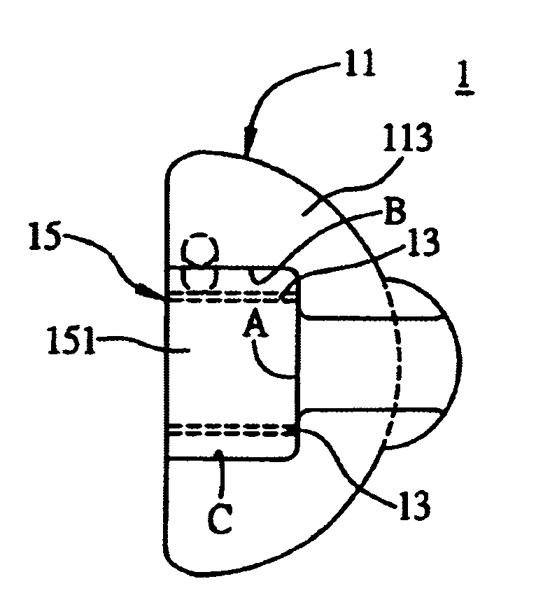
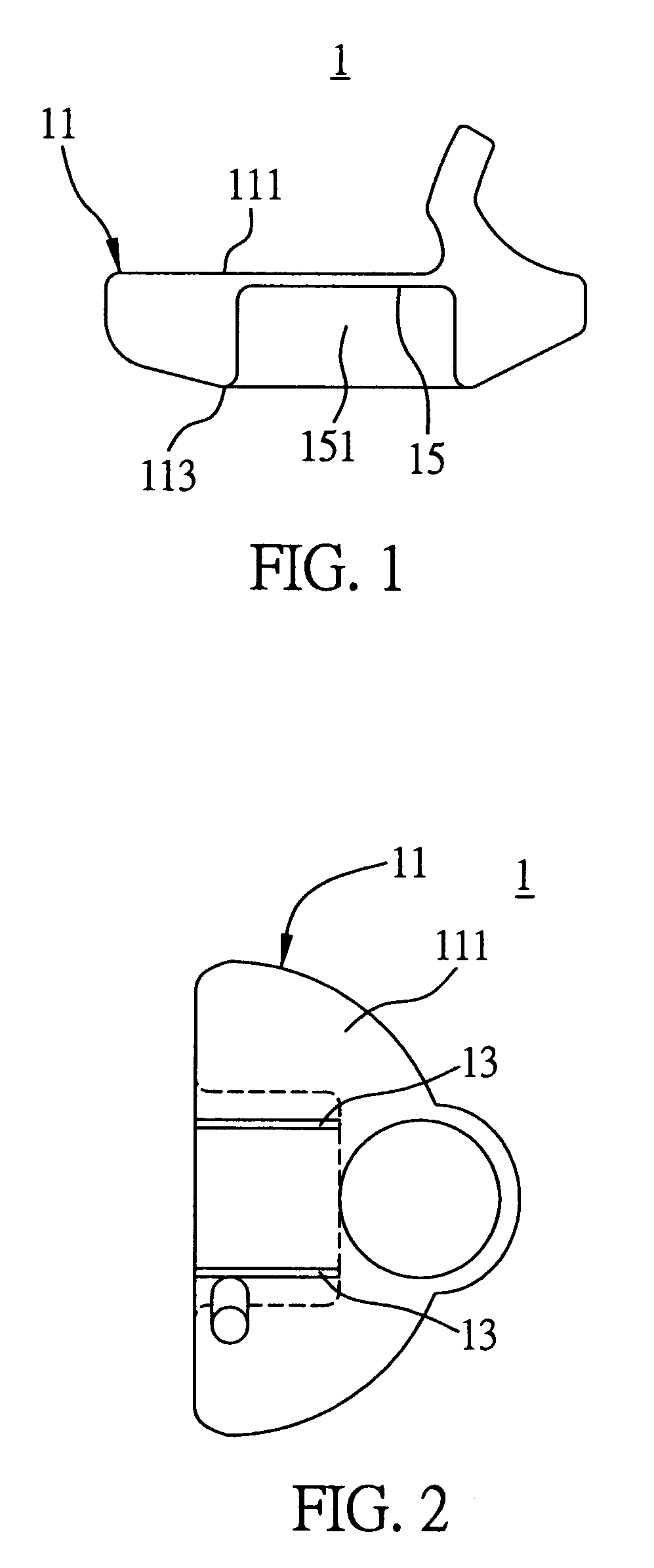
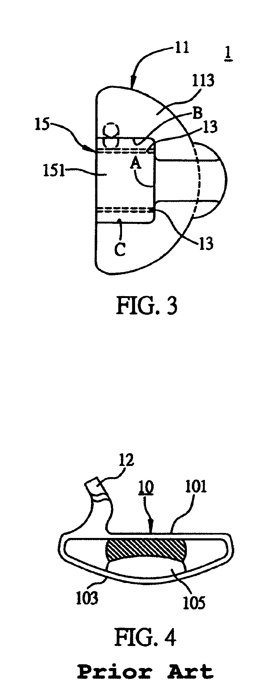
[0021]The preferred embodiment for a gold club head proposed by the present invention is described in detail with reference to FIGS. 1 to 3. As shown, the golf cub head 1 particularly used in a putter comprises a body 11, an aligning portion 13, and a striking portion 15.

[0022]The golf club head 1 can be designed as a conventional D-type club head having a thicker bottom. Since the inclination, length, and weight (dependent on the fabrication materials) of a club head are well known in the art and thus not to be further discussed herein.

[0023]Referring to FIG. 1, the body 11 of the club head 1 is formed with a top surface 111 and a bottom surface 113, wherein the top surface 11 is substantially flat while the bottom surface 113 has the conventional inclination.

[0024]Referring to FIG. 2, the aligning portion 13 is formed on the top surface 111 of the body 11 and has an indicative means for aligning a golf ball (not shown) with an intended movement path toward a target hole, wherein t...


PUM


Abstract

A golf club head for use in a putter includes: a body having a top and a bottom, an aligning portion formed on the top of the body, and a striking portion having a cavity and formed on the bottom of the body. By using the aligning portion to align a golf ball with an intended movement path toward a target hole, the golf ball can be hit by the striking portion to move along the intended path toward the target hole.

Description

FIELD OF THE INVENTION[0001]The present invention relates to golf club heads, and more particularly, to a club head of a golf putter to improve the performance and posture of a golfer when playing golf.BACKGROUND OF THE INVENTION[0002]It is well recognised that putting is usually considered as the determining factor of victory or defeat in a golf game. Putting is implemented by combination of feeling, tactile sensations, and experience. During putting, in order to allow a golf ball to reach a target hole, a golfer must operate a putter to strike and propel the golf ball accurately that is urged to move in an optimal topspin motion toward the target hole on the green in such a way that the putter face striking the ball is perpendicular to an intended movement path of the ball toward the target.[0003]FIG. 4 shows a common club head 10 of a golf putter. The club head 10 comprises a top portion 101, a bottom portion 103 and a recessed portion 105. The top portion 101 of the club head 10...

Claims


Application Information

Patent Timeline
Patent Type & Authority Patents(United States)
IPC IPC(8): A63B69/36A63B53/04A63B53/08
CPCA63B53/0487A63B53/08A63B2053/0441A63B60/00A63B53/0441
Inventor WANG, MA-LI
Owner JIAN SHING TECH
Learn More