Pivoted tensiometer for measuring tension in an intervertebral disc space

a technology of intervertebral disc space and tensiometer, which is applied in the field of tensiometer for measuring tension in intervertebral disc space, can solve the problems of reducing device accuracy, reducing reliability, and low back pain, and achieve the effect of accurate measuremen

Active Publication Date: 2006-03-21
DEPUY ACROMED INC
View PDF16 Cites 25 Cited by
  • Summary
  • Abstract
  • Description
  • Claims
  • Application Information

AI Technical Summary

Benefits of technology

[0010]This embodiment is advantageous over the Niwa-type devices in that the pivot does not jam.
[0011]This embodiment is advantageous over the Arcan device because the change in distance between the proximal portions of the longitudinal members is much generally greater than that occurring about the pivot, and so can be much more accurately measured. Accordingly, the report of the corresponding loads associated with this change in distance may be much more accurate.

Problems solved by technology

The leading cause of lower back pain arises from rupture or degeneration of lumbar intervertebral discs.
The subjectivity of this method may reduce its reliability.
However, since the distal end of the movable arm is subjected to a significant resisting force (from the resisting ligaments), the beam portion of the movable arm may jam in its corresponding hole, thereby reducing the accuracy of the device.
However, since the load cell is disposed about the pivot, the actual change in distance recorded by the load cell is small.
Since the reported load is based upon this small change in distance, a small inaccuracy in recorded distance may lead to an inaccurate report of load.

Method used


Image

  • Pivoted tensiometer for measuring tension in an intervertebral disc space
  • Pivoted tensiometer for measuring tension in an intervertebral disc space
  • Pivoted tensiometer for measuring tension in an intervertebral disc space

Examples


Embodiment Construction

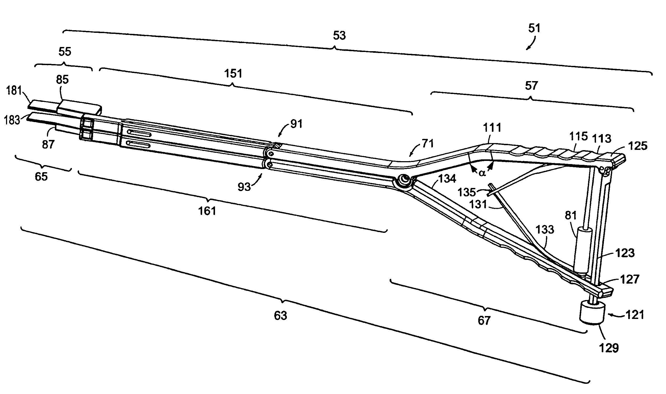
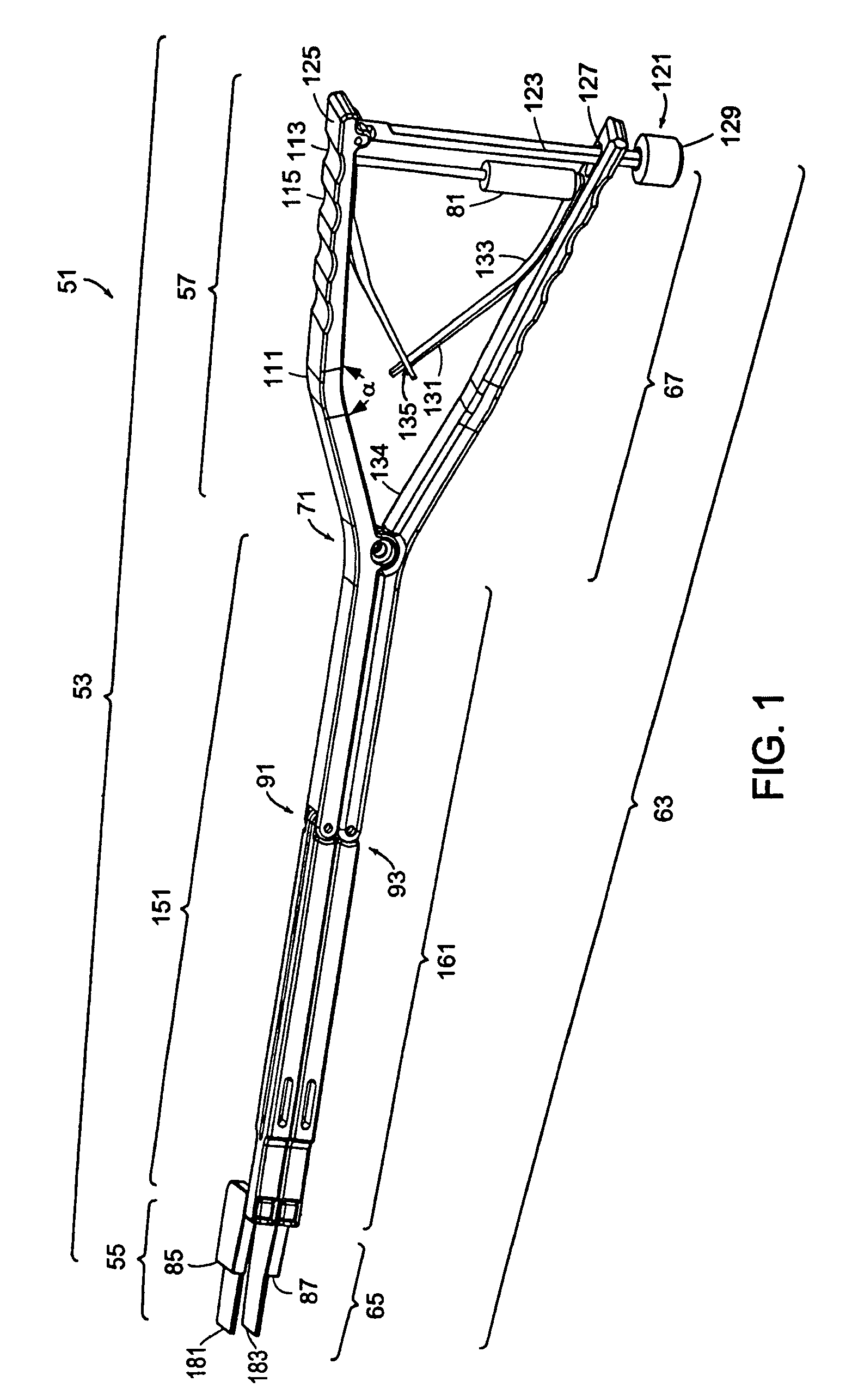
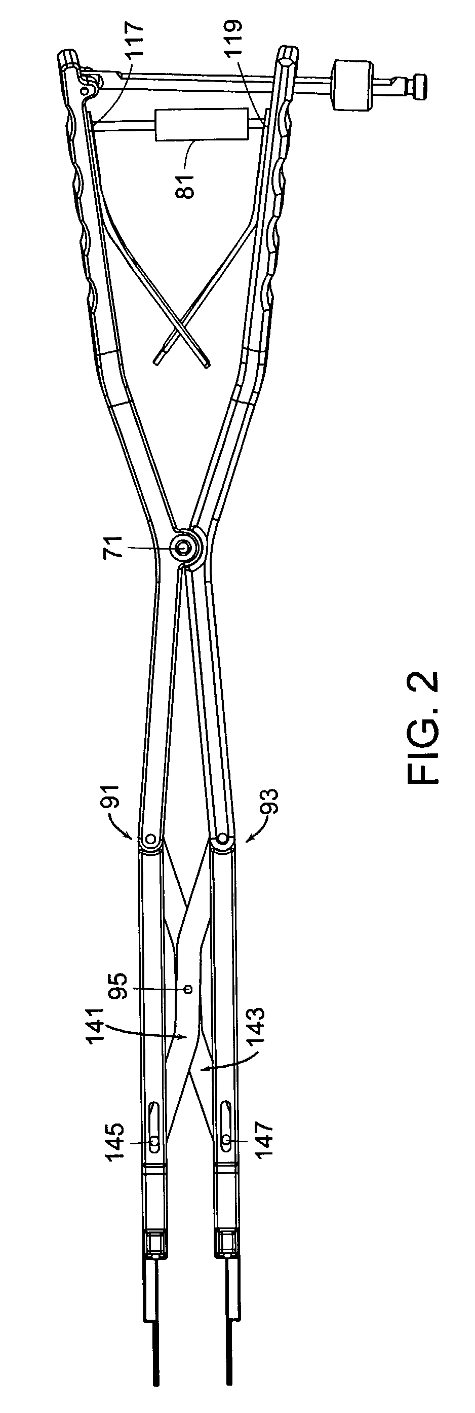
[0023]For the purposes of the present invention, the term “supporting structures” refers to the ligaments and portions of the annulus fibrosus surrounding the disc space that experience tension when an inplant is inserted into the disc space. The term “disc space” refers to the space between opposing intervertebral bodies when at least a portion of the nucleus pulposus has been removed.

[0024]Now referring to FIGS. 1–3, there is provided a tensiometer 51 for measuring tension in an intervertebral disc space, comprising:[0025]a) a first longitudinal member 53 having a distal end portion 55 adapted for engaging a first vertebral surface, an intermediate portion 151, and a proximal handle portion 57 having an attachment point 117,[0026]b) a second longitudinal member 63 having a distal end portion 65 adapted for engaging a second vertebral surface, an intermediate portion 161, and a proximal handle portion 67 having an attachment point 119, the first and second longitudinal members bein...


PUM

PropertyMeasurementUnit
angleaaaaaaaaaa
angleaaaaaaaaaa
distanceaaaaaaaaaa

Abstract

The present invention relates to a novel pivoted tensiometer adapted for use in measuring tension in an intervertebral disc space.

Description

BACKGROUND OF THE INVENTION[0001]The leading cause of lower back pain arises from rupture or degeneration of lumbar intervertebral discs. Pain in the lower extremities is caused by the compression of spinal nerve roots by a bulging disc, while lower back pain is caused by collapse of the disc and by the adverse effects of bearing weight through a damaged, unstable vertebral joint. One conventional method of managing these problems is to remove the problematic disc and replace it with a prosthetic implant (such as a fusion body, spacer or a motion disk) within the intervertebral disc space.[0002]Generally, intervertebral implant technology relies upon tension provided by natural ligaments adjacent the disc space to keep the implant in place. Accordingly, prior to insertion of the implant, it is typically desirable to measure the degree of tension afforded by these natural ligaments. However, a prevalent manner of measuring intervertebral tension requires the surgeon to insert a distr...

Claims


Application Information

Patent Timeline
Patent Type & Authority Patents(United States)
IPC IPC(8): A61B5/103A61B5/00A61B17/02G01L1/04A61B19/00A61F2/44A61F2/46
CPCA61B19/46A61B2017/0256A61F2002/4666A61F2/442A61F2002/4622A61B2019/464A61B2090/064A61B90/06
Inventor GRINBERG, ALEXANDER
Owner DEPUY ACROMED INC
Why Eureka
Try Eureka