X-ray imaging apparatus

Inactive Publication Date: 2006-03-21
CANON KK
View PDF7 Cites 51 Cited by
  • Summary
  • Abstract
  • Description
  • Claims
  • Application Information

AI Technical Summary

Benefits of technology

[0015]Under the above-described situations, an object of the present invention is

Problems solved by technology

Therefore, it is difficult to make the electronic cassette compact and lightweight as compared to the film cassette.
This leads to an additional increase in the size and weight of the electronic cassette.
The condition of the patient P is so bad that he or she cannot be brought to an X-ray room in which a stationary X-ray imaging apparatus is installed.
However,

Method used


Image

  • X-ray imaging apparatus
  • X-ray imaging apparatus
  • X-ray imaging apparatus

Examples


first embodiment

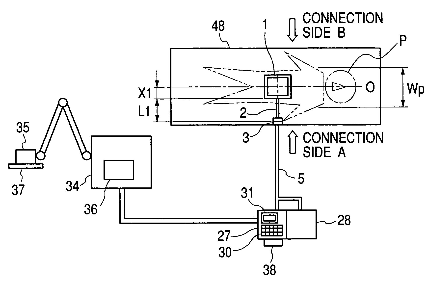
[0041]FIGS. 1A and 1B are diagrams showing the structure of a Parts equivalent to those in the previously mentioned drawings will be designated by the same reference characters.

[0042]What is different in this embodiment from the electronic cassette 49 shown in FIG. 6 is that a cable 2 is connected to the case of an electronic cassette 1 and a connector 3 is provided at the end of the cable 2. In FIG. 1B, L1 represents the distance from the side surface of the electronic cassette 1 to which the cable 2 is connected to the end of the cable 3, and X1 represents the distance from the center C of the imaging area 4 of the electronic cassette 1 to the aforementioned side surface of the electronic cassette 1. The electronic cassette 1 has a connection port for the cable 2 provided on the aforementioned side surface. In FIG. 1A, Wp represents the shoulder width or the maximum body width defined by Japanese Industrial Standards (JIS) Z8500 (directed to measurement of human body), and line O...

second embodiment

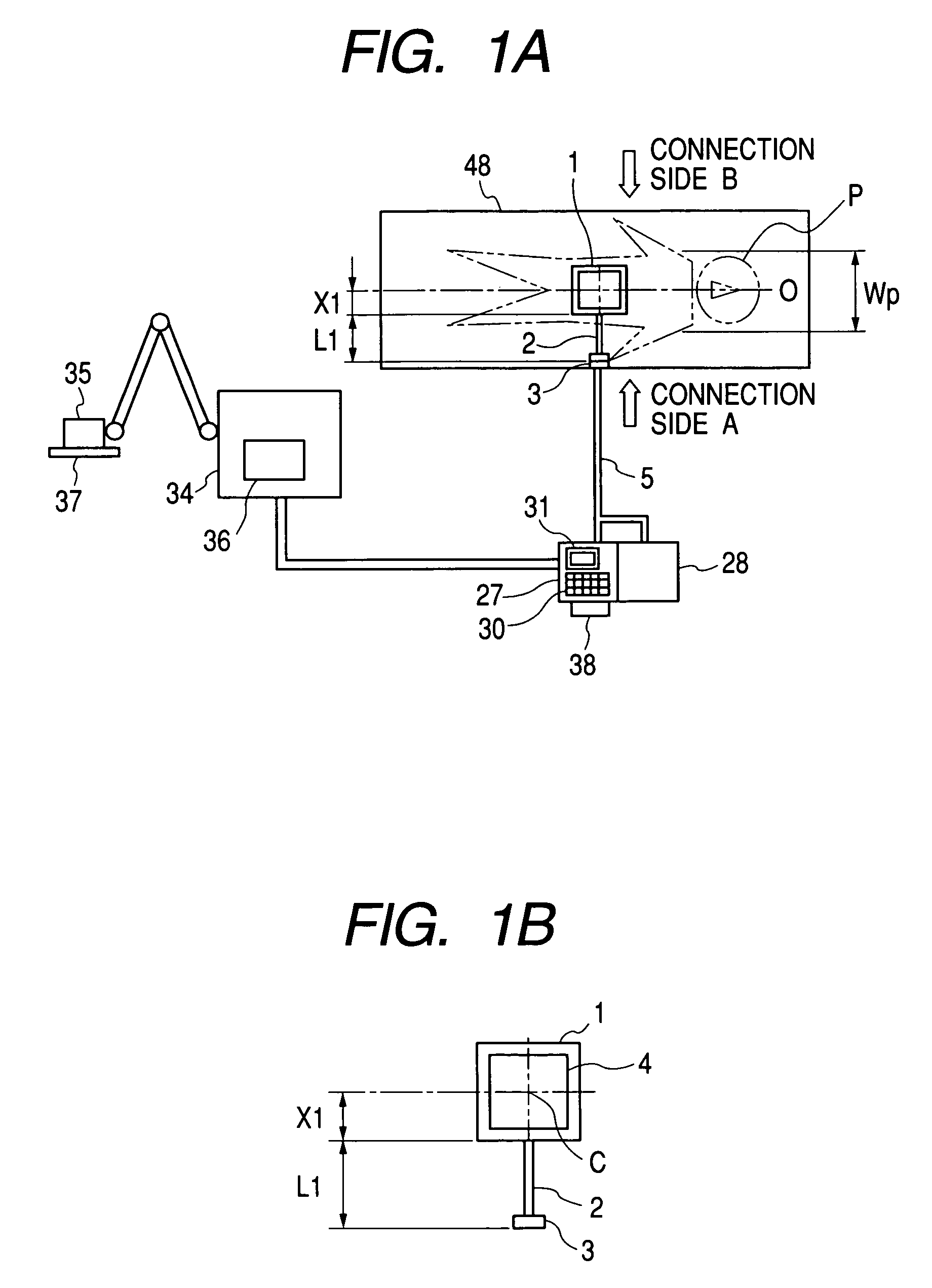
[0046]FIG. 2 is a diagram showing the structure of the present invention. In FIG. 2, the parts same as those in the previously mentioned drawings are designated by the same reference characters.

[0047]What is different in this embodiment from the electronic cassette 1 shown in FIGS. 1A and 1B is that the electronic cassette has a substantially rectangular shape, the connection port for a cable 7 is provided on a long side of it, and a connector 8 is provided at the end of the cable 7. The imaging area 9 also has a substantially rectangular shape. In the situation shown in FIG. 2, the electronic cassette 6 is disposed in such a way that its long side is perpendicular to the center line of the body axis O of the patient P. Therefore, the connection port for the cable 7 can hardly be visually observed, since it is beneath the body of the patient P. However, letting L2 be the distance from the side surface of the electronic cassette 6 to which the cable 7 is connected to the end of the c...

third embodiment

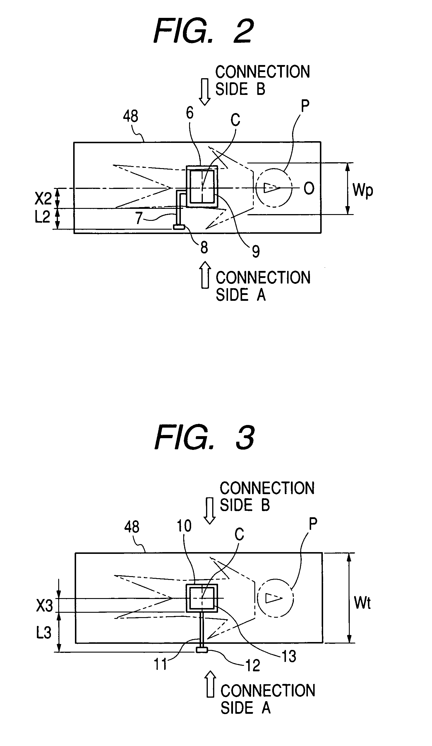
[0049]FIG. 3 is a diagram showing the structure of the present invention. In FIG. 3, the parts same as those in the previously mentioned drawings are designated by the same reference characters.

[0050]What is different in this embodiment from the electronic cassette 49 shown in FIG. 6 is that a cable 11 is connected to the case of an electronic cassette 10 and a connector 12 is provided at the end of the cable 11. In FIG. 3, L3 represents the distance from the side surface of the electronic cassette 10 facing the connection side A to the end of the cable 12, and X3 represents the distance from the center C of the imaging area 13 of the electronic cassette 10 to the aforementioned side surface of the electronic cassette 10. The electronic cassette 10 has a connection port for the cable 11 provided on the aforementioned side surface. In addition, Wt represents the width of the bed 48. Specifically, the width Wt represents the width of the bed 48 in the direction perpendicular to the bo...


PUM


Abstract

An electronic cassette accommodating a sensor for converting radiation into an electric signal. A cable with a specific length is connected to a side surface of the electronic cassette. A connector that is connectable with a wireless communication unit or an external power source is provided at an end of the cable.

Description

BACKGROUND OF THE INVENTION[0001]1. Filed of the Invention[0002]The present invention relates to an X-ray imaging apparatus used for medical diagnosis and particularly relates to a portable imaging apparatus having an area sensor serving as an X-ray receiving medium in which multiple photoelectric conversion elements are two-dimensionally arranged on the same plane.[0003]2. Related Background Art[0004]It is a widely used method, in the field of nondestructive inspection for industrial purpose and in the field of medical diagnosis, to obtain a radiation image of an object to be imaged by irradiating the object to be imaged with radiation and detecting the intensity distribution of the radiation that has been transmitted through the object to be imaged. Specifically, a general method of obtaining a radiation image of an object includes the steps of preparing a combination of a silver film and a so-called fluorescent screen (or an intensifying screen) that emits fluorescent light upon ...

Claims


Application Information

Patent Timeline
IPC IPC(8): H01L27/146G01T1/00A61B6/00G01T7/00G03B42/02H01L31/115H04L29/08H04N5/225H04N5/32
CPCA61B6/00A61B6/542H04L67/12A61B6/544A61B6/548E06B9/54E06B9/581E06B9/60E06B9/78E06B2009/527
Inventor YAMAMOTO, OSAMU
Owner CANON KK
Why Eureka
Try Eureka