Disk device

a technology of a disk and a housing is applied in the field of disk devices, which can solve the problems of suppressing a gear ratio, affecting the freedom of selecting the gear ratio, and raising the manufacturing cos

Inactive Publication Date: 2006-03-21
FUNAI ELECTRIC CO LTD
View PDF2 Cites 2 Cited by
  • Summary
  • Abstract
  • Description
  • Claims
  • Application Information

AI Technical Summary

Benefits of technology

[0013]An object of the present invention is to provide a disk device in which three operations including a rotary operation of the rotary tray, an operation of chucking on and off by the chucking mechanism and an operation of taking in and out the slide tray are conducted by one motor, without using a conventional planetary gear mechanism having an internal gear and an elastic force of the elastic member for chucking on and off. The disk device is capable of solving the aforementioned problems of the layout and deterioration on stability of recording and playback.
[0014]It is another object of the present invention to provide a disk device capable of continuously conducting an operation of taking in and out (opening / closing) the slide tray, an operation of rotating the rotary tray intermittently and an operation of chucking on and off by the chucking mechanism at an appropriate timing.
[0018]In the present invention, it is possible to adopt the following structure. The motor and the central gear rotated by the motor are arranged on the slide tray, and the idler gear is pivotally attached to a connecting member pivotally connected with a support shaft of the central gear so that the idler gear can be always engaged with the central gear. In the case of adopting the above structure, it is preferable that the disk device further comprises an idler gear posture maintaining member for maintaining a state of engagement of the idler gear with the rack when the slide tray is taken in and out, wherein the idler gear posture maintaining member is arranged in the device body. Due to the above structure, the idler gear is meshed with the rack for taking in and out. Therefore, the slide tray can be stably taken in and out. When the central gear is combined with the idler gear in the present invention so that power generated by the motor is selectively transmitted to the motive gear or the rack for taking in and out, it is possible to arbitrarily determine a gear ratio of the central gear to the idler gear. Therefore, the freedom of selecting the gear ratio can be enhanced.

Problems solved by technology

However, three operations including a rotary operation of the rotary tray, an operation of chucking on and off by the chucking mechanism and an operation of taking in and out the slide tray are not conducted by one motor.
Therefore, the manufacturing cost is raised.
Therefore, the following problems may be encountered in the disk device.
Accordingly, there is a restriction in suppressing a gear ratio of the internal gear to the planetary gear, and the freedom of selecting the gear ratio is remarkably limited.
Therefore, when the disk is chucked (clamped) by the chucking mechanism, an impact shock is generated.
Thus the disk interferes with the rotary tray by the shock, which causes a problem.
Further, the following problems may be encountered.
Since an elastic force generated by the elastic member fluctuates, when the disk is chucked by the elastic force generated by the elastic member so that recording or playback can be conducted, the rotating disk oscillates and interferes with the rotary tray.
This deteriorates stability of recording or playback.

Method used


Image

  • Disk device
  • Disk device
  • Disk device

Examples


Embodiment Construction

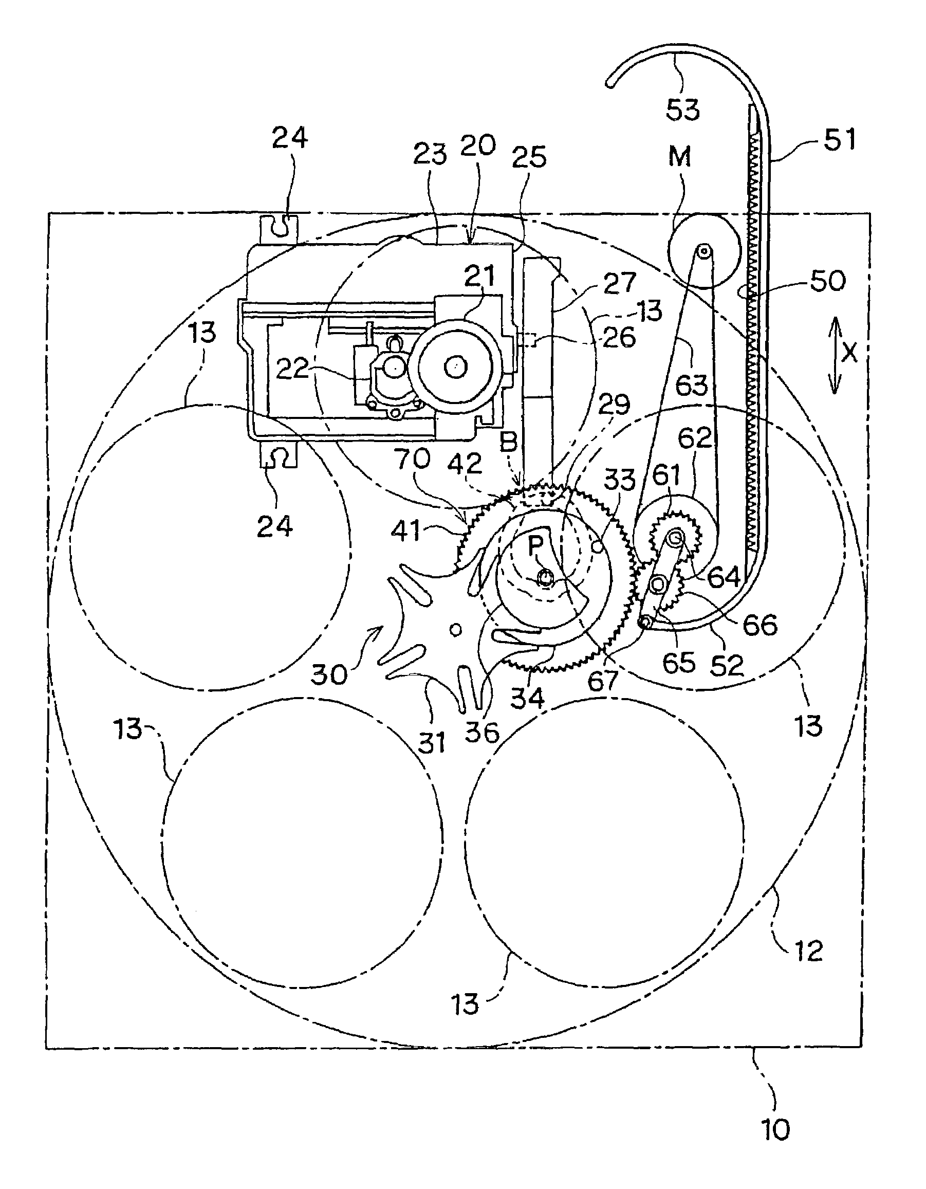
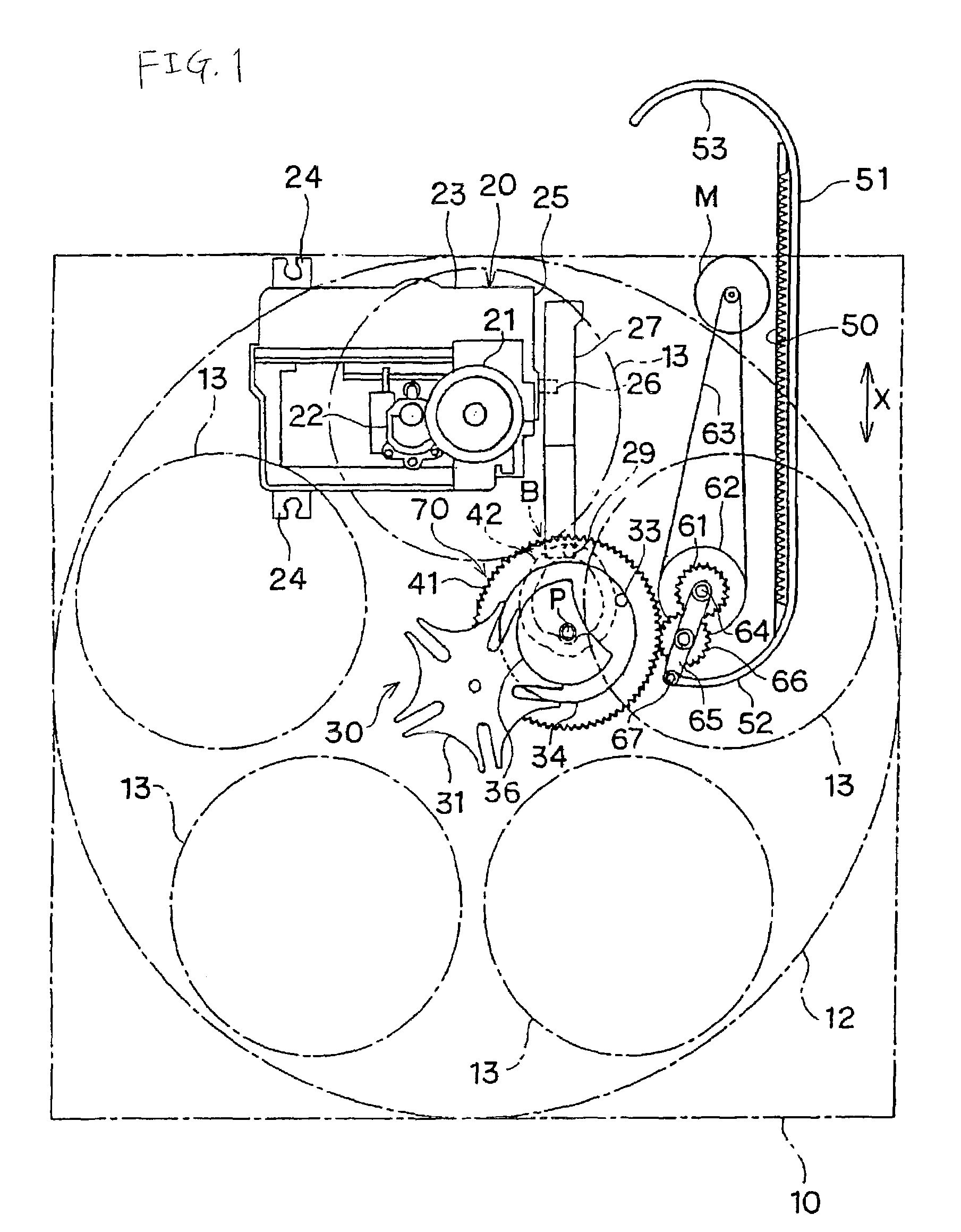
[0038]FIG. 1 is a schematic illustration showing a primary portion of an embodiment of the disk device of the present invention. In FIG. 1, reference numeral 10 is a substantially rectangular slide tray. This slide tray is slidably attached to a device body not shown in the drawing. When this slide tray 10 is drawn out to the front from the device body, it is defined as an open state. When this slide tray 10 is drawn back into the device body, it is defined as a closed state. In FIG. 1, the slide tray 10 in the open state is shown. On this slide tray 10, there is provided a disk-shaped rotary tray 12 which is pivotally arranged. The rotary tray 12 includes a plurality of circular disk setting sections 13 which are arranged at a plurality of positions at regular angular intervals in the circumferential direction. In the example shown in the drawing, the plurality of circular disk setting sections 13 are arranged at five positions. Each disk setting section 13 is provided with an open...


PUM

PropertyMeasurementUnit
poweraaaaaaaaaa
rotationaaaaaaaaaa
diameteraaaaaaaaaa

Abstract

A disk device has a slide tray, rotary tray and chucking mechanism. A motive gear attached to the slide tray has an engaging pin. On the rotary tray, a Geneva gear operating in cooperation with the engaging pin is provided. In a motive gear, a cam groove and a cam member for controlling ON and OFF of chucking operation are provided. In a device body, there are provided a rack for taking in and out and a guide groove. There are provided a central gear driven by motor and an idler gear meshed with the central gear. According to a rotation direction of the motor, the idler gear is selectively meshed with the motive gear or the rack.

Description

BACKGROUND OF THE INVENTION[0001]1. Field of the Invention[0002]The present invention relates to a disk device, particularly to a disk device on which a rotary disk exchanger mechanism is mounted.[0003]2. Description of the Related Art[0004]In this type of disk device, a rotary tray having a plurality of disk setting sections in the circumferential direction is mounted on a slide tray which is taken in and out from a device body. A disk which is set at each disk setting section on the rotary tray is chucked by a chucking mechanism at a disk scanning position when rotation of the rotary disk is stopped. An operation of taking in and out the slide tray, an operation of rotating the rotary tray so as to move a disk, which is set at a predetermined disk setting section, to a disk scanning position and an operation of chucking on and off at the disk scanning position are all conducted by utilizing power generated by motors.[0005]In this type of disk device, it is conventional that a rota...

Claims


Application Information

Patent Timeline
Patent Type & Authority Patents(United States)
IPC IPC(8): G11B17/03G11B17/24G11B17/22
CPCG11B17/226
Inventor IWAASA, HIROAKI
Owner FUNAI ELECTRIC CO LTD
Why Eureka
Try Eureka