Prime mover output control system

a technology of output control and prime mover, which is applied in the direction of process and machine control, electric generator control, instruments, etc., can solve the problems that the generator output cannot be avoided, and achieve the effect of preventing excessive fluctuations, reducing noise, and magnifying fluctuation rather than suppressing

Inactive Publication Date: 2007-03-15
MITSUBISHI ELECTRIC CORP
View PDF10 Cites 1 Cited by
  • Summary
  • Abstract
  • Description
  • Claims
  • Application Information

AI Technical Summary

Benefits of technology

[0006] Because conventional prime mover control systems have been configured as described above, it has been possible to eliminate noise included in a rotating-speed detection signal and to prevent excessive fluctuations; however, the conventional prime mover control systems directly respond to power fluctuation components, other than those due to noise, that occur between a generator and a power system, thereby controlling the increase or decrease in prime mover output torque, there has been a case where, depending on a timing when the prime mover output torque fluctuates, the fluctuation is magnified rather than suppressed. Moreover, in a method in which a dead-time function is provided, there has been a problem in that, because actual hunting attenuates or increases its amplitude, thereby causing a difference between a past deviation outputted from the dead-time function and the present deviation, the control signal is not zero, whereby the hunting of the generator output can not be avoided due to the difference.
[0007] The present invention has been implemented in order to solve the foregoing problems; it is an object to provide a prime mover control system that can prevent magnification of power fluctuation, included in a feedback signal, that occurs between a generator and a power system, and that enables stable operation to continue, without disturbing the power system.
[0008] The present invention provides a prime mover output control system in which, in the case where a deviation detection device that receives as input an output-power command value signal indicating a command value that is a target for the output power of a generator driven by a prime mover and an output power signal indicating the present value of the output power, and that outputs a deviation signal indicating the deviation between the command value and the present value of the output power, and in the case where a control device that receives as an input the deviation signal and outputs a control output signal for controlling the output of the prime mover, a filtering device is incorporated that, in the output power signal, the deviation signal, or the control output signal, attenuates or eliminates predetermined frequency components caused by periodic fluctuations, in the output power of a generator, that occur due to discrepancy between the output of the prime mover and the generator output power.
[0009] Fluctuation components, in the output power of a generator, that do not require control of a prime mover, and if unnecessarily controlled, rather deteriorates stability of the power system, are attenuated or eliminated by means of a filtering device; therefore, it is possible to prevent the output of the prime mover from unnecessarily responding to fluctuations in output power of the generator, thereby magnifying the fluctuation in the output power.

Problems solved by technology

Moreover, in a method in which a dead-time function is provided, there has been a problem in that, because actual hunting attenuates or increases its amplitude, thereby causing a difference between a past deviation outputted from the dead-time function and the present deviation, the control signal is not zero, whereby the hunting of the generator output can not be avoided due to the difference.

Method used


Image

  • Prime mover output control system
  • Prime mover output control system
  • Prime mover output control system

Examples


embodiment 1

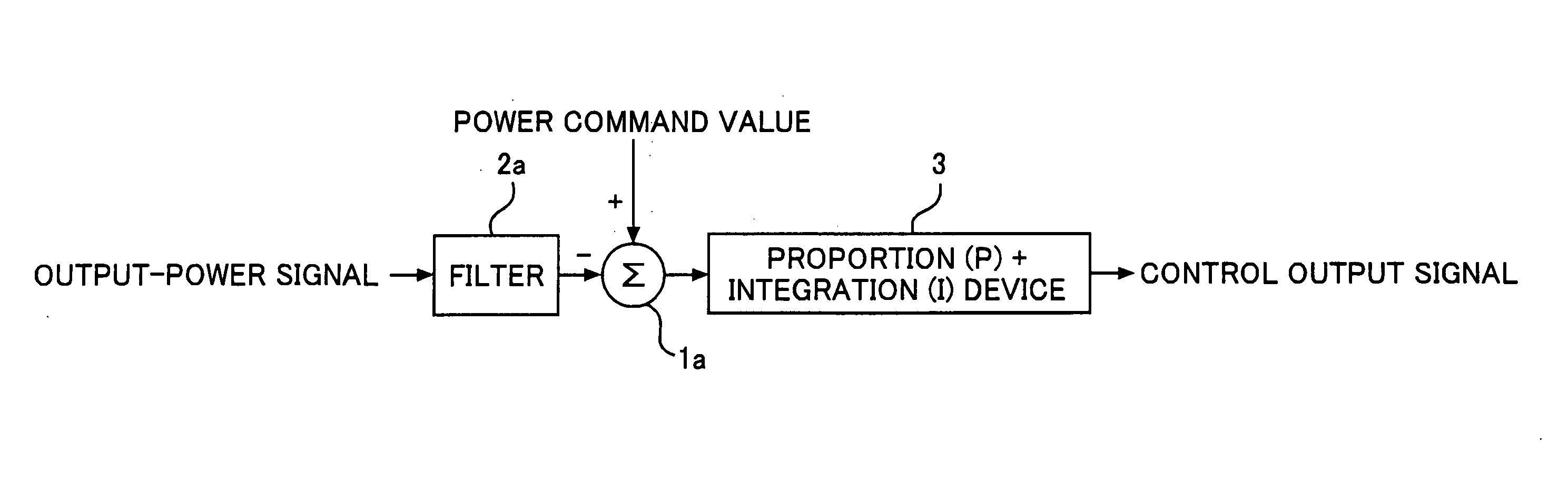
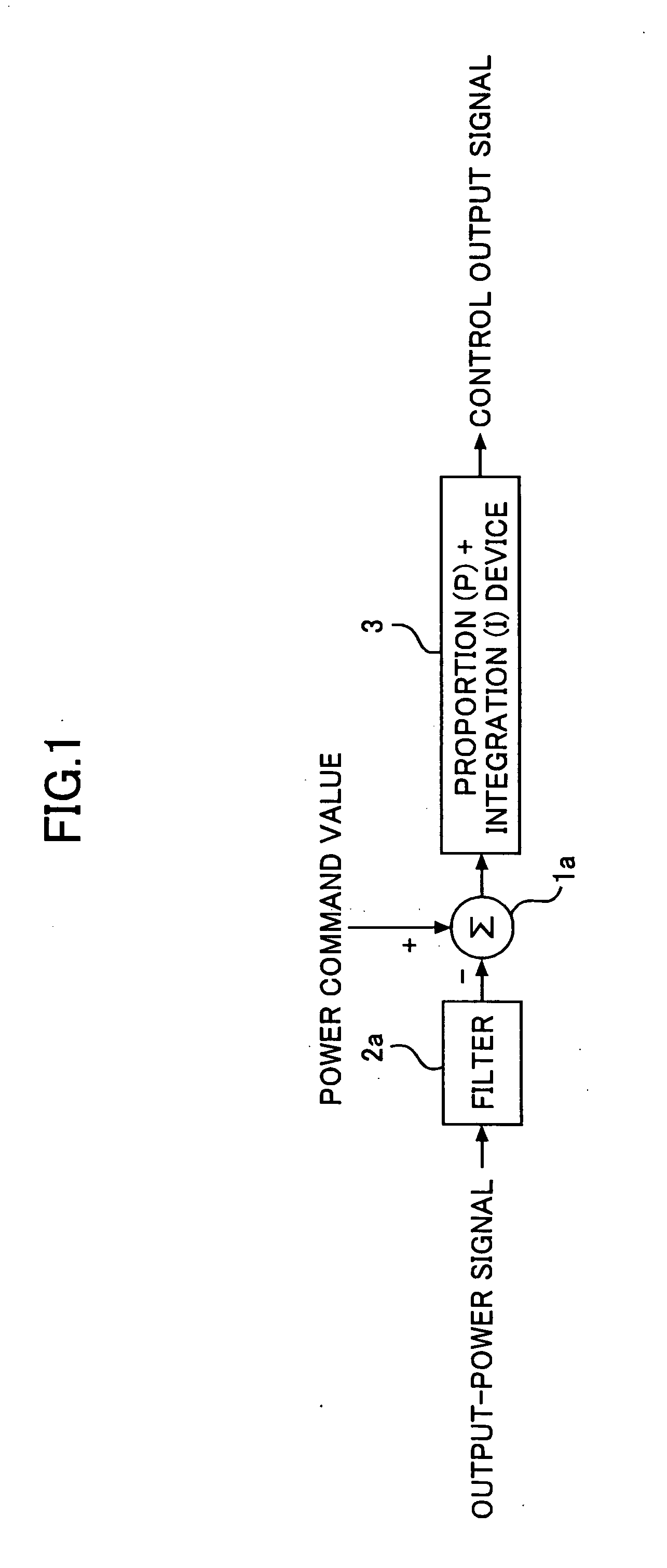
[0025]FIG. 1 is a block diagram illustrating a control method for a prime mover control system, of a power-generating system, according to Embodiment 1 of the present invention. In FIG. 1, an electric-power command value, which is forwarded in accordance with a demand / supply plan to the power-generating system and is a command value as a target for output power, is inputted to a difference detection device 1a; an output-power signal, which is utilized as a feedback signal and indicates the present value of output power of a generator (unillustrated), is also inputted by way of a filtering device 2a to the deviation detection device 1a. The deviation detection device 1a obtains the difference between the electric-power command value and the filtered output-power signal and outputs a difference signal. Based on the difference signal outputted by the deviation detection device 1a, a PI circuit 3, which is an example of a control device for adjusting responsiveness and stability of a co...

embodiment 2

[0048] In Embodiment 1, a method has been described in which the magnification of power fluctuation is prevented by attenuating or eliminating fluctuation components that does not require response; however, in Embodiment 2, a control method will be described in which the unnecessary fluctuation is positively suppressed.

[0049]FIG. 4 is a block diagram illustrating a control method for a prime mover control system according to Embodiment 2 of the present invention. In FIG. 4, in place of the filtering device 2a in FIG. 1, a phase adjustment device 6a configured of a lag-lead network (1+T1·s) / (1+T2·s) and the like is arranged before the PI circuit 3. The adjustment of the phase is similar to that in Embodiment 1, and eventually implemented on the basis of an actual apparatus.

[0050] In the phase adjustment device 6a, by changing increase and decrease, in the output of the prime mover, for the fluctuation of the output power Pe of the generator in such a way as to occur at the followin...

embodiment 3

[0055] In Embodiment 2, a method has been described in which, in order to adjust the timing at which the output of the prime mover is increased or decreased, the phase adjustment device 6a is arranged in series with a control device; however, in Embodiment 3, a method will be described in which, by adding a circuit that responds only to fluctuation components in the output power of the generator, thereby positively increasing or decreasing the output of the prime mover, the fluctuation in the output power of the generator is suppressed.

[0056]FIG. 5 is a block diagram illustrating a control method for a prime mover control system according to Embodiment 3 of the present invention. The configuration in FIG. 5 is obtained by, to the configuration in FIG. 1, adding a change detection device 7a for detecting changing components in the output-power signal, a phase adjustment device 8a, and a addition device 9a for adding up the output of the PI circuit 3 and the output of the phase adjus...


PUM

PropertyMeasurementUnit
frequencyaaaaaaaaaa
frequencyaaaaaaaaaa
output poweraaaaaaaaaa

Abstract

A prime mover control system is provided that can prevent magnification of power fluctuation, included in a feedback signal, that occurs between a generator and a power system, and that enables stable operation of the prime mover to continue, without disturbing the power system. In the case where a deviation detection device (1a) that receives as input an output-power command value signal indicating a command value that is a target for the output power of a generator driven by a prime mover and an output-power signal indicating the present value of the output power, and that outputs a deviation signal indicating the deviation between the command value and the present value of the output power, and in the case where a control device (3a) that receives as an input the deviation signal and outputs a control output signal for controlling the output of the prime mover, a filtering device (2a) is provided that, in the output-power signal, the deviation signal, or the control output signal, attenuates or eliminates predetermined frequency components caused by periodic fluctuations, in the output power of a generator, that occur due to discrepancy between the output of the prime mover and the generator output power.

Description

BACKGROUND OF THE INVENTION [0001] 1. Field of the Invention [0002] The present invention relates to a prime mover output control system for a power-generating system in which, by means of a prime mover such as a water turbine, a steam turbine, a gas turbine, or an engine, a generator is rotated to generate electric power. [0003] 2. Description of the Related Art [0004] In a conventional control system for prime mover output (mechanical) torque, there has been a problem in that, because a rotating speed detection signal includes white noise, such as sensor noise, and colored noise due to precession movement of a generator, whereby a signal is always outputted, a control system for prime mover output (mechanical) torque operates; therefore, in order to eliminate these types of noise, limitation of output, a dead band, and a band-pass filter are provided (e.g., Japanese Laid-Open Patent Publication No. 2002-233195, Paragraphs 0017 through 0025, FIG. 1). [0005] In addition, there has b...

Claims


Application Information

Patent Timeline
Patent Type & Authority Applications(United States)
IPC IPC(8): H02P9/04
CPCH02P9/04H02P2101/10Y10T29/5171
Inventor SHIMOMURA, MASARU
Owner MITSUBISHI ELECTRIC CORP
Why Eureka
Try Eureka