Component connection system

a connection system and component technology, applied in the direction of screws, threaded fasteners, snap fasteners, etc., can solve the problems of affecting the connection system, etc., to achieve the effect of improving the disconnect of the components of the connection system

Inactive Publication Date: 2006-03-28
ILLINOIS TOOL WORKS INC
View PDF14 Cites 100 Cited by
  • Summary
  • Abstract
  • Description
  • Claims
  • Application Information

AI Technical Summary

Benefits of technology

[0010]The present invention solves problems and overcomes drawbacks and deficiencies of prior art component connection systems by providing a novel method and apparatus for automobile component connection and removal allowing for an improved disconnect of the components of the connection system, while also allowing for proper retention and connection between the components.
[0015]Another feature of the present invention is to provide a system that can be serviced completely from the exterior of a vehicle.

Problems solved by technology

One drawback of this conventional connection system becomes apparent during automobile servicing involving the removal of components affixed using w-based clips.
However, such access rarely is available.
This method, which is often the most widely employed to remove components utilizing w-based clips, frequently results in damage to the w-based clip, and / or the affixed components, such as, for example, the associated sheet metal panel.
Due to cost related factors, damaged components are often scrapped and replaced with new components, which can significantly increase the cost of a routine repair.
However, this solution has drawbacks in that slots are significantly more expensive to punch compared to holes, and access behind the sheetmetal panel is still needed to facilitate removal of any affixed components.
These prior-art references do not provide an adequate means of component separation without the resulting damage to the attachment means and / or the components themselves.
These prior-art references also disclose fasteners and the like including multiple elements which render the relatively complex designs thereof prone to failure and therefore unfeasible for use with automobile components.

Method used


Image

  • Component connection system
  • Component connection system
  • Component connection system

Examples


Embodiment Construction

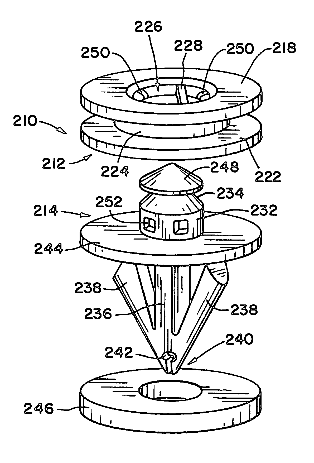
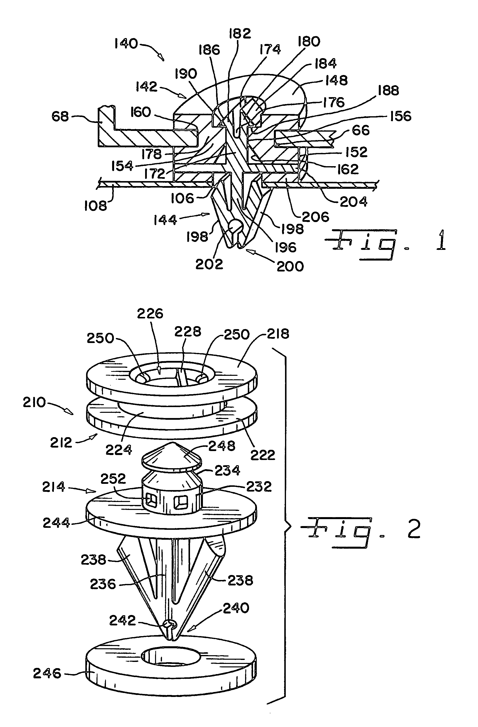
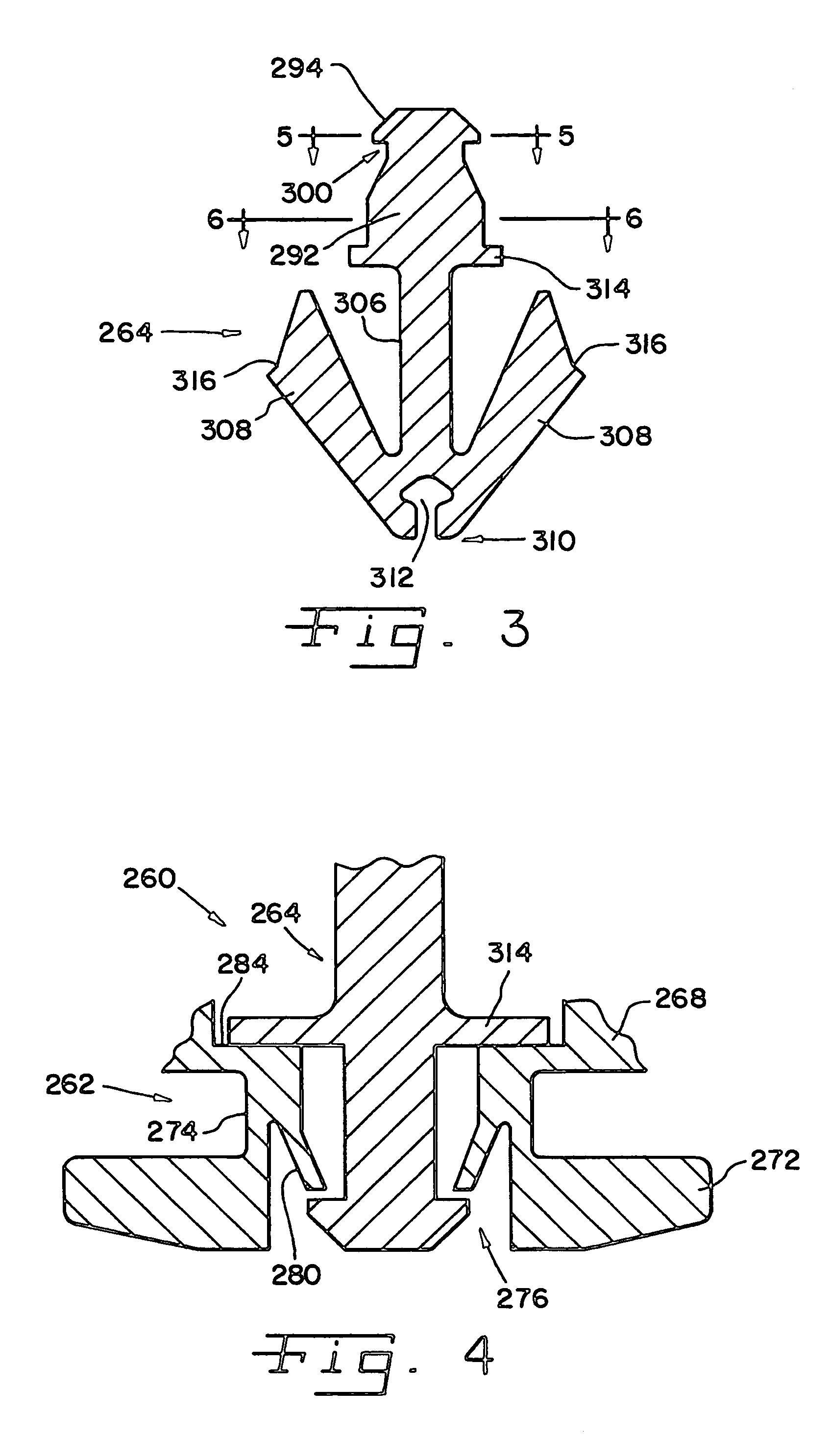
[0026]Referring now to the drawings wherein like reference numerals designate corresponding parts throughout the several views, FIGS. 1–7 illustrate component connection systems according to the present invention.

[0027]Component connection system 140 (FIG. 1) includes a female clip member 142 and a male clip member 144. Female clip member 142 includes first and second flanges 148 and 152, respectively, joined by a centrally located neck 154. First and second flanges 148 and 152, respectively, and neck 154, may be manufactured as a single component or as separate components and joined thereafter. A slot 156 along the central axis of female clip member 142 includes a peripheral ledge 160 provided in first flange 148 and an inwardly tapering entrance surface 162 in second flange 152. Female clip member 142 includes a generally circular, or alternatively a rectangular profile when viewed in the direction of the longitudinal axis of slot 156. Those skilled in the art will appreciate, in ...


PUM


Abstract

A multi-component connection system suitable for automobiles includes a female clip member having a slot, and a male clip member having a male element insertable within the slot. The slot and male element include mutually engageable cooperative structures. A shank connected to the male element includes wings mounted at a distal end and capable of resilient lateral deflection relative to the longitudinal axis of the shank. The female clip member may be affixed to a first component and the male clip member may be insertable within a hole in a second component so as to connect the two components when the male clip member is inserted in the hole, the male element is disposed within the slot, and the cooperative structures are engaged.

Description

CROSS-REFERENCE TO RELATED APPLICATIONS[0001]The present regular application claims benefit to United States Provisional Application Ser. No. 60 / 434,065 filed Dec. 17, 2002.FIELD OF THE INVENTION[0002]The present invention relates generally to assemblies for connecting automobile components, and, more particularly to a novel clip design that provides superior installation, removal and servicing capabilities for automobile components.BACKGROUND OF THE INVENTION[0003]Historically, claddings, wheel lips, bodyside moldings and other exterior trim components on automobiles have been attached using various clips, such as conventional “w-based” clips. An exemplary conventional connection system installation using such w-based clips includes an exterior component affixed to a sheetmetal panel by means of the w-based clip. The installation process generally includes drilling or punching a hole or slot in the sheetmetal panel and subsequent insertion and snap-fitting of wings of the w-based c...

Claims


Application Information

Patent Timeline
Patent Type & Authority Patents(United States)
IPC IPC(8): F16B5/00E04F19/02F16B21/08B60R13/02B60R13/04F16B5/06F16B21/07
CPCB60R13/0206F16B5/065F16B21/084F16B21/086E04F19/02F16B21/071Y10T24/309Y10T24/42F16B21/073
Inventor KURILY, BRETTSCROGGIE, DEREK
Owner ILLINOIS TOOL WORKS INC
Why Eureka
Try Eureka