Reversible ratchet-type wrench

a ratchet wrench and ratchet-type technology, which is applied in the direction of wrenches, manufacturing tools, spanners, etc., can solve the problems of reducing the torque-bearing capacity of the ratchet wrench, troublesome disengagement of the ring spanner, and the inability to operate the ring spanner in the reverse direction

Inactive Publication Date: 2006-03-28
HU BOBBY
View PDF207 Cites 18 Cited by
  • Summary
  • Abstract
  • Description
  • Claims
  • Application Information

AI Technical Summary

Benefits of technology

[0008]It is, therefore, an objective of the present invention to provide a ratchet-type wrench that allows reversible operations without the risk of movement of a switching member for switching the ratcheting direction.

Problems solved by technology

However, the ring spanners could not be operated in a reverse direction and thus require troublesome disengagement of the ring spanner from the fastener and reengagement of the ring spanner until tightening / loosening of the fastener is achieved.
However, the formation of top and bottom ratchet teeth on a side of the restrictive teeth structure would not be easy, and this decreases the torque-bearing capacity of the ratchet wrench, as the meshing area between the restrictive teeth structure and the ratchet wheel is reduced.
Further, the restrictive teeth structure could not be reliably positioned, as there is no positioning means provided between the rotating disc and the wrench body.
Further, the engaging force between the ratchet wheel and the rotating disc provided by a C-shaped fastening ring was found to be poor.
However, the overlapped portion results in a thin wall thickness (L) of the head 20′, which adversely affects the torque-bearing capacity.
This would increase the difficulty of manufacture.
The threaded vertical section 82″ of the switching member 8″ and the screw hole 33″ of the pawl 3″ result in difficulty in manufacture and assembly.

Method used


Image

  • Reversible ratchet-type wrench
  • Reversible ratchet-type wrench
  • Reversible ratchet-type wrench

Examples


Embodiment Construction

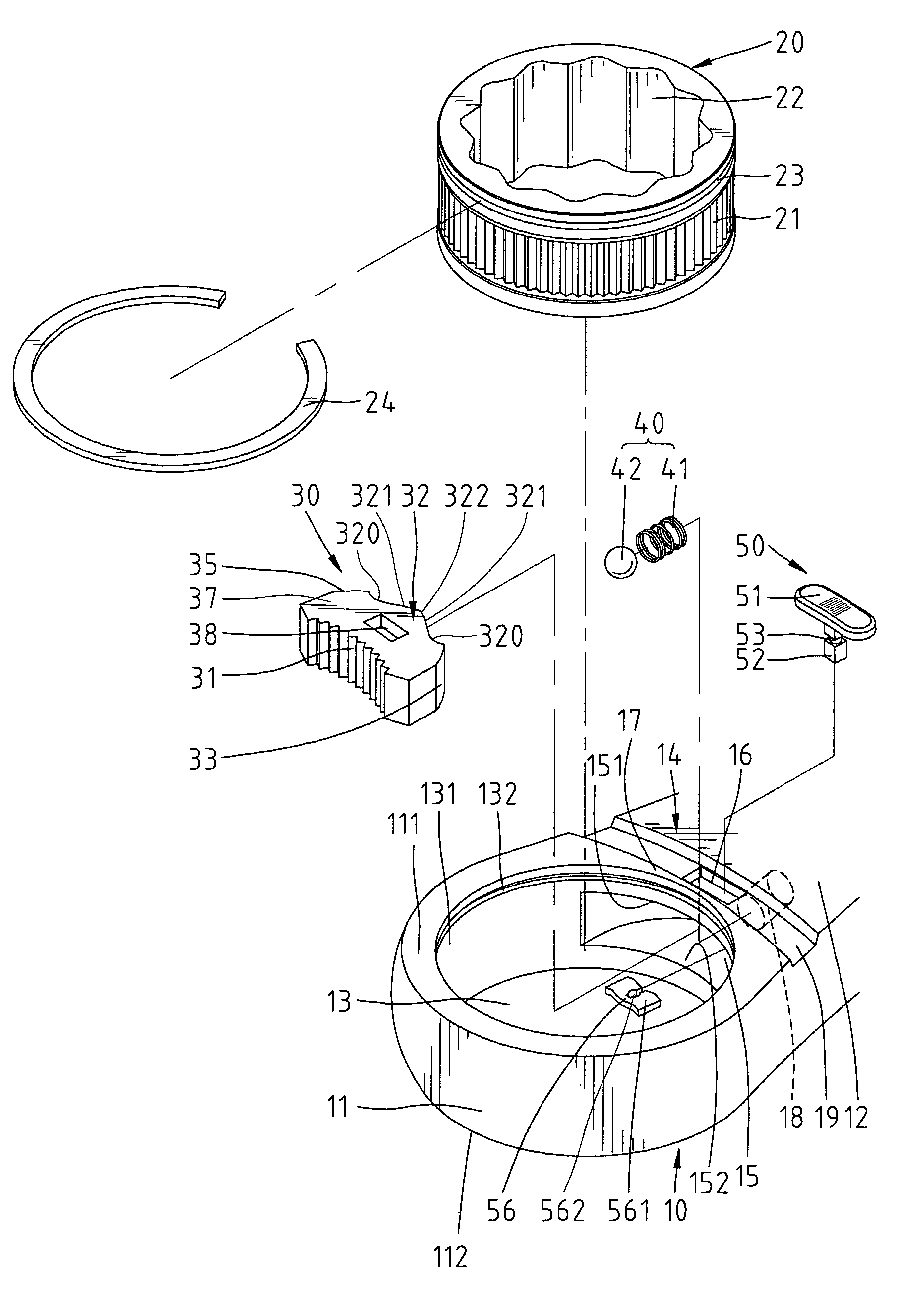
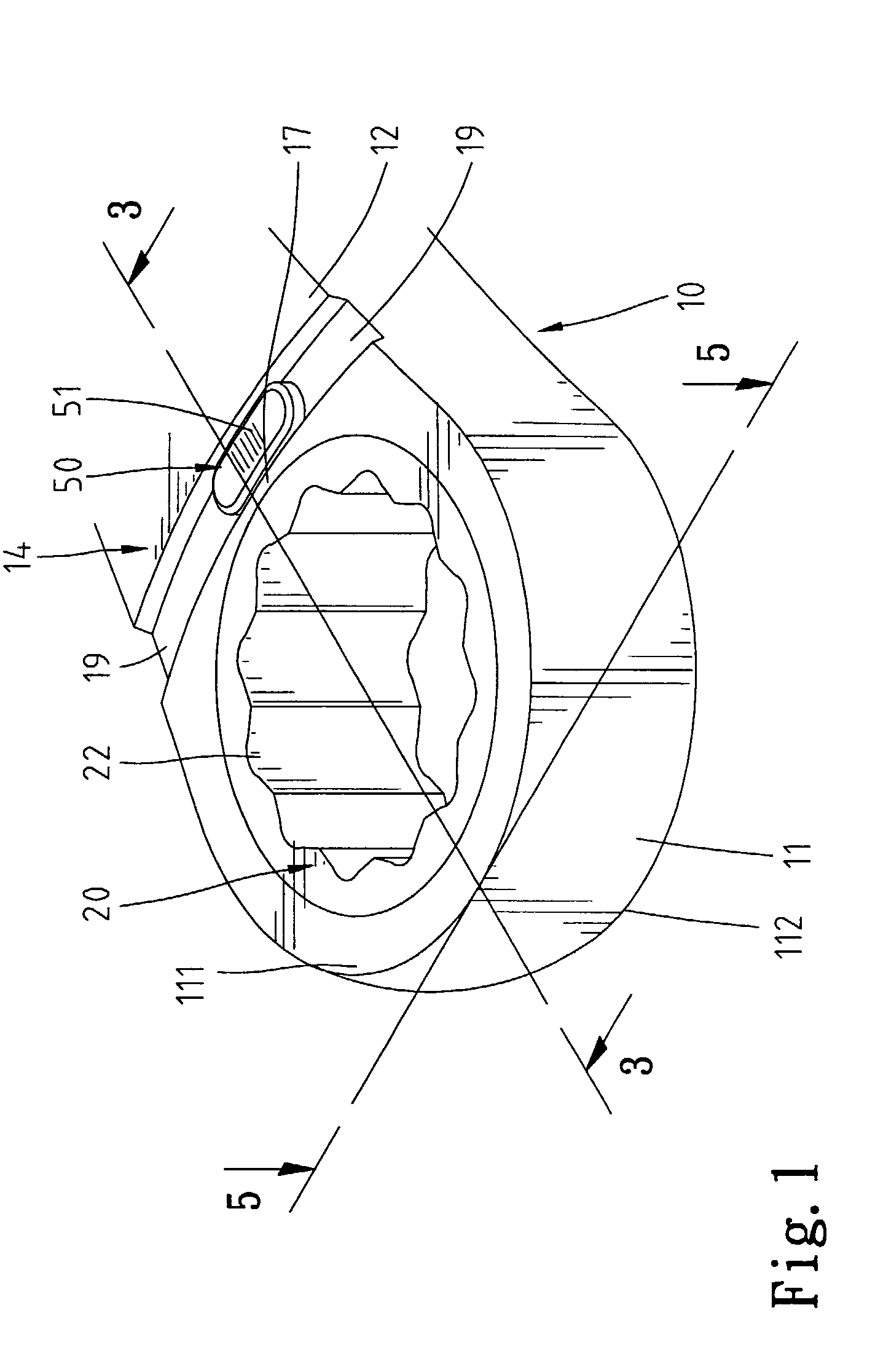
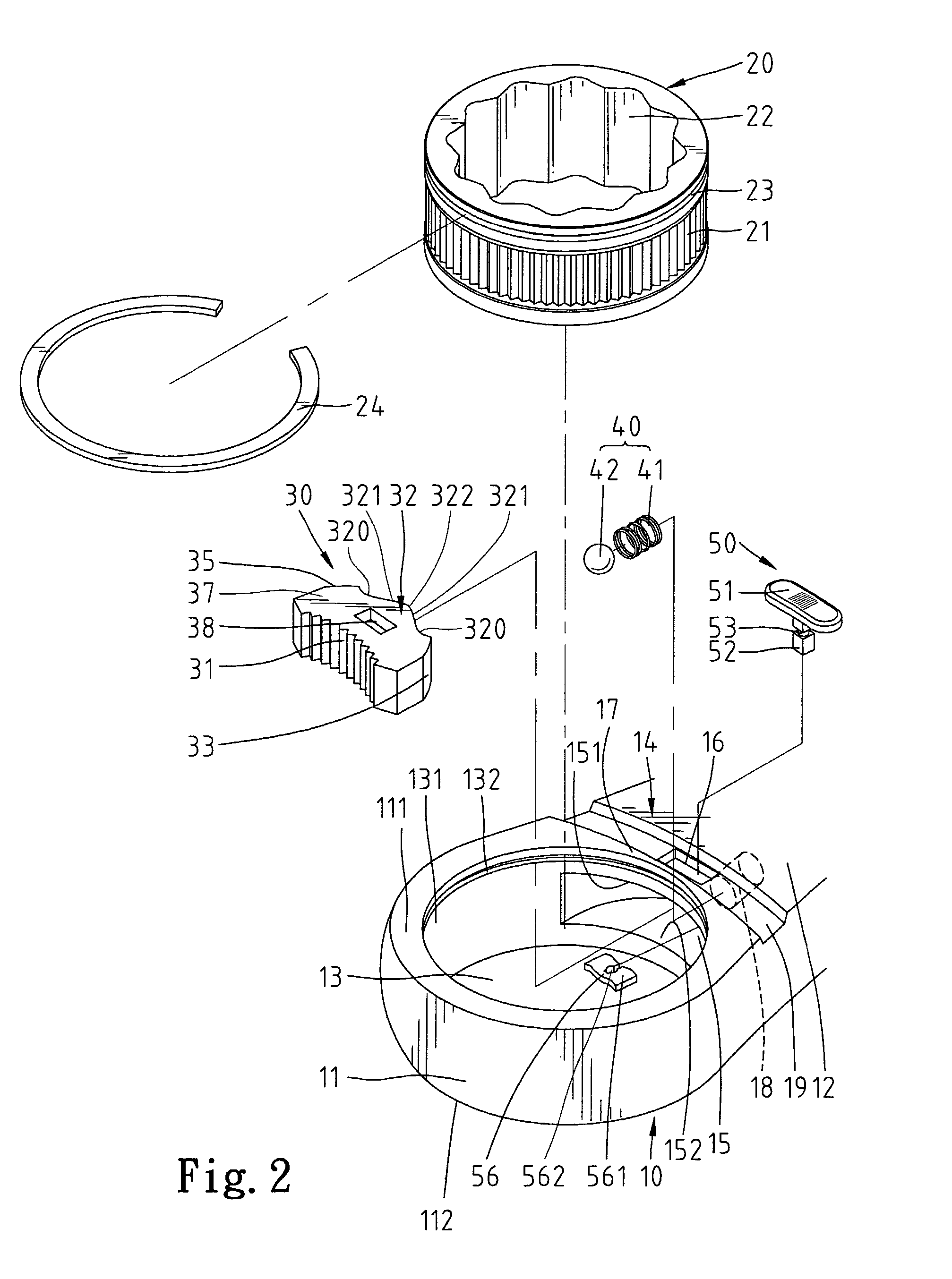
[0040]Referring to FIGS. 1 through 3, a reversible ratchet-type wrench in accordance with the present invention is designated by “10” and generally comprises a handle 12 and a head 11 extending from the handle 12. A web 14 is defined between the handle 12 and the head 11. A hole 13 is defined in the head 11 and extends from a top face 111 to a bottom face 112 of the head 11. A compartment 15 is defined in the web 14 and communicated with the hole 13 of the head 11. As illustrated in FIGS. 2 and 3, the compartment 15 is delimited by an upper wall 151, a bottom wall 152, and a peripheral wall 153. A receptacle 18 is defined in the peripheral wall 153 of the compartment 15 and faces the hole 13.

[0041]An opening (or slot or hole) 16 is defined in a side of the web 14 (i.e., the upper wall 151 of the compartment 15) and communicated with the compartment 15. In this embodiment, a transverse channel 19 is defined in the side of the web 14 and extends from a lateral side of the web 14 throu...


PUM


Abstract

A wrench includes a handle, a head extending from the handle and having a hole for rotatably receiving a drive member, and a web defined between the handle and the head. The web includes a side and a compartment communicated with the hole of the head. An opening is defined in the side of the web and communicated with the compartment. A pawl is slidably received in the compartment and includes a recessed portion. A switching member has a first end for manual operation and a second end extending through the opening of the web into the recessed portion of the pawl. The recessed portion of the pawl and the second end of the switching member are so configured that the switching member is not moved when the pawl moves as a result of free rotation of the wrench.

Description

BACKGROUND OF THE INVENTION[0001]1. Field of the Invention[0002]The present invention relates to a reversible ratchet-type wrench. In particular, the present invention relates to a ratchet-type wrench that allows reversible operations without the risk of movement of a switching member for switching the ratcheting direction.[0003]2. Description of the Related Art[0004]Wrenches are an important hand tool and have many types such as spanners, adjusting wrenches, combination wrenches, and socket wrenches. Ring spanners are very useful when the fastener to be tightened / loosened is located in a difficult-to-access place. However, the ring spanners could not be operated in a reverse direction and thus require troublesome disengagement of the ring spanner from the fastener and reengagement of the ring spanner until tightening / loosening of the fastener is achieved.[0005]U.S. Pat. No. 6,220,123 to Chen issued on Apr. 24, 2001 discloses a structure of a ratchet wrench comprising a ratchet whee...

Claims


Application Information

Patent Timeline
Patent Type & Authority Patents(United States)
IPC IPC(8): B25B13/46
CPCB25B13/463
Inventor HU, BOBBY
Owner HU BOBBY
Why Eureka
Try Eureka