Pull-type suspension

a pull-type, suspension technology, applied in the direction of shock absorbers, cycle equipment, transportation and packaging, etc., can solve the problems of motorcycles being harsh over bumps and wallowing on the normal road, inconvenience and cost of adding a separate gas chamber

Inactive Publication Date: 2006-03-28
VINCENZO F COSTA
View PDF4 Cites 29 Cited by
  • Summary
  • Abstract
  • Description
  • Claims
  • Application Information

AI Technical Summary

Benefits of technology

This patent describes a device used to control how much movement there is at the back of a motorcycle when it moves over uneven surfaces. It uses hydraulic technology to adjust this movement based on what kind of surface they're riding on. There are two parts: a cylinder with a piston inside it, which helps absorb some of the shocks, and another part called a spring piston which squeezes air between them to further help absorb shocks. By adjusting a valve in the system, the device can change the way quickly the oil flows within the chambers, thus changing the level of resistance provided by the suspension. Overall, this makes it easier to ride smoothly no matter what type of terrain you encounter while driving your motorcycle.

Problems solved by technology

The technical problem addressed in this patent text relates to improving the design of suspension systems for motorcycles. Current methods often result in uncomfortable rides and limited control over suspension stiffness. Additionally, current designs may include expensive components like gas chambers or complicated mechanisms. There is a need for a new suspension system that eliminates the requirement for gas chambers, allows for easier adjustments, provides consistent damping, and simplifies usage.

Method used


Image

  • Pull-type suspension
  • Pull-type suspension
  • Pull-type suspension

Examples


Embodiment Construction

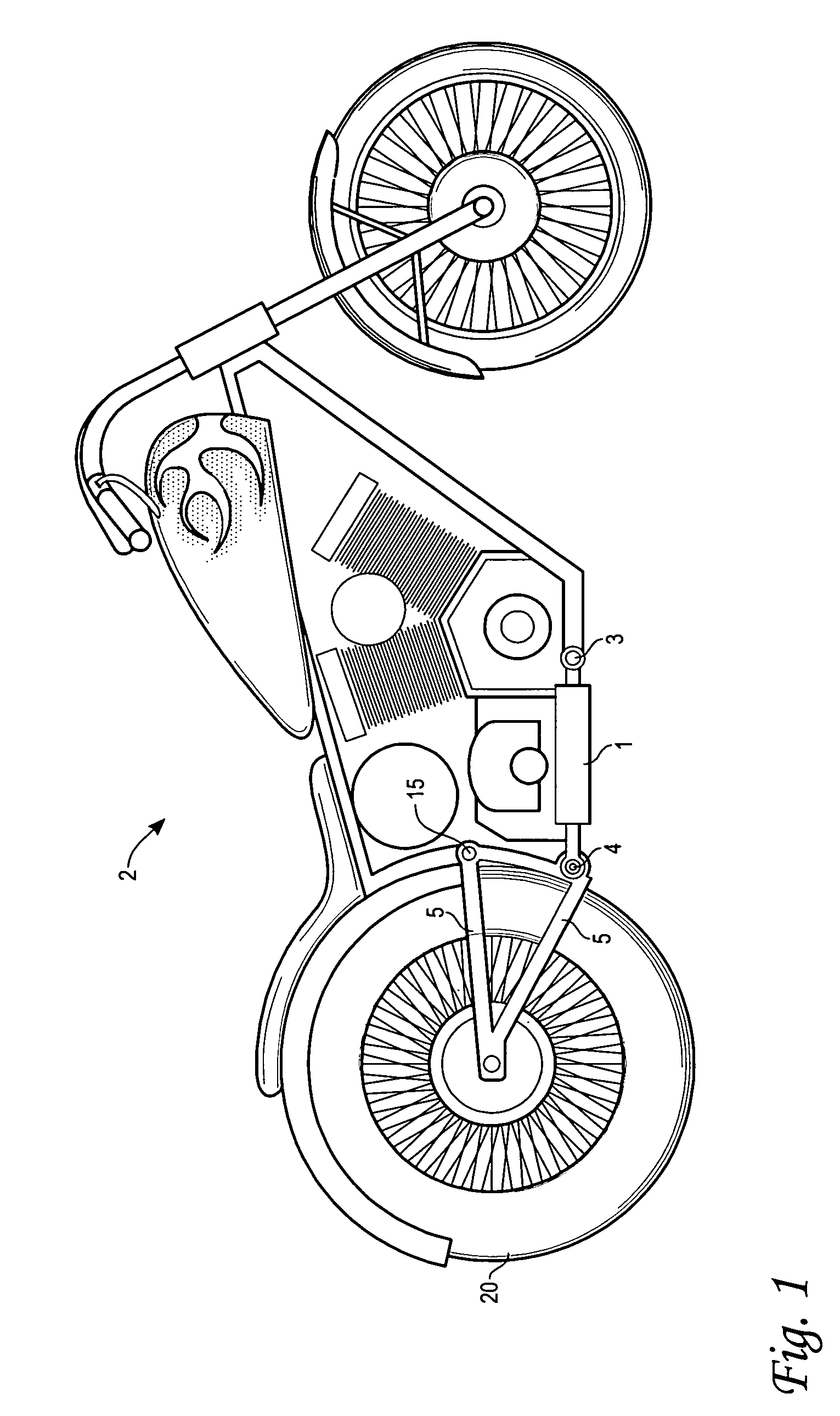
[0014]The present invention embodies a number of features and innovations that make it useful as a suspension unit. FIG. 1 illustrates how the suspension unit is mounted in a motorcycle 2. The suspension unit 1 is attached to the swingarm 5 below a swingarm pivot 15 at a swingarm mount 4. As such, compression of a rear wheel 20 causes an extension of the suspension unit 1, and extension of the wheel away from the motorcycle 2 causes a compression of the suspension unit 1.

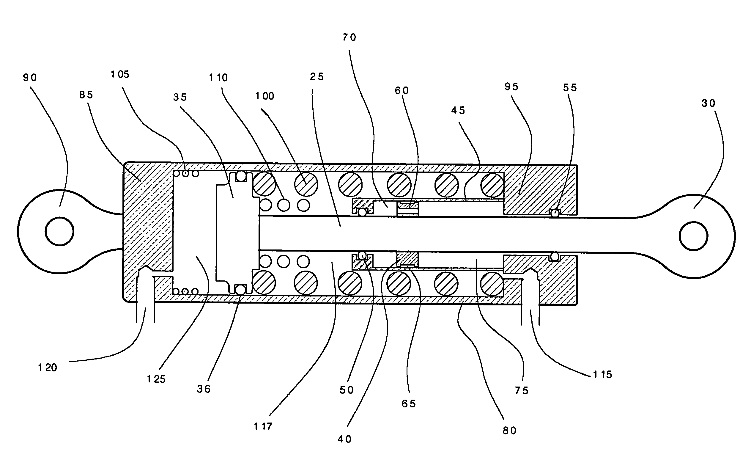
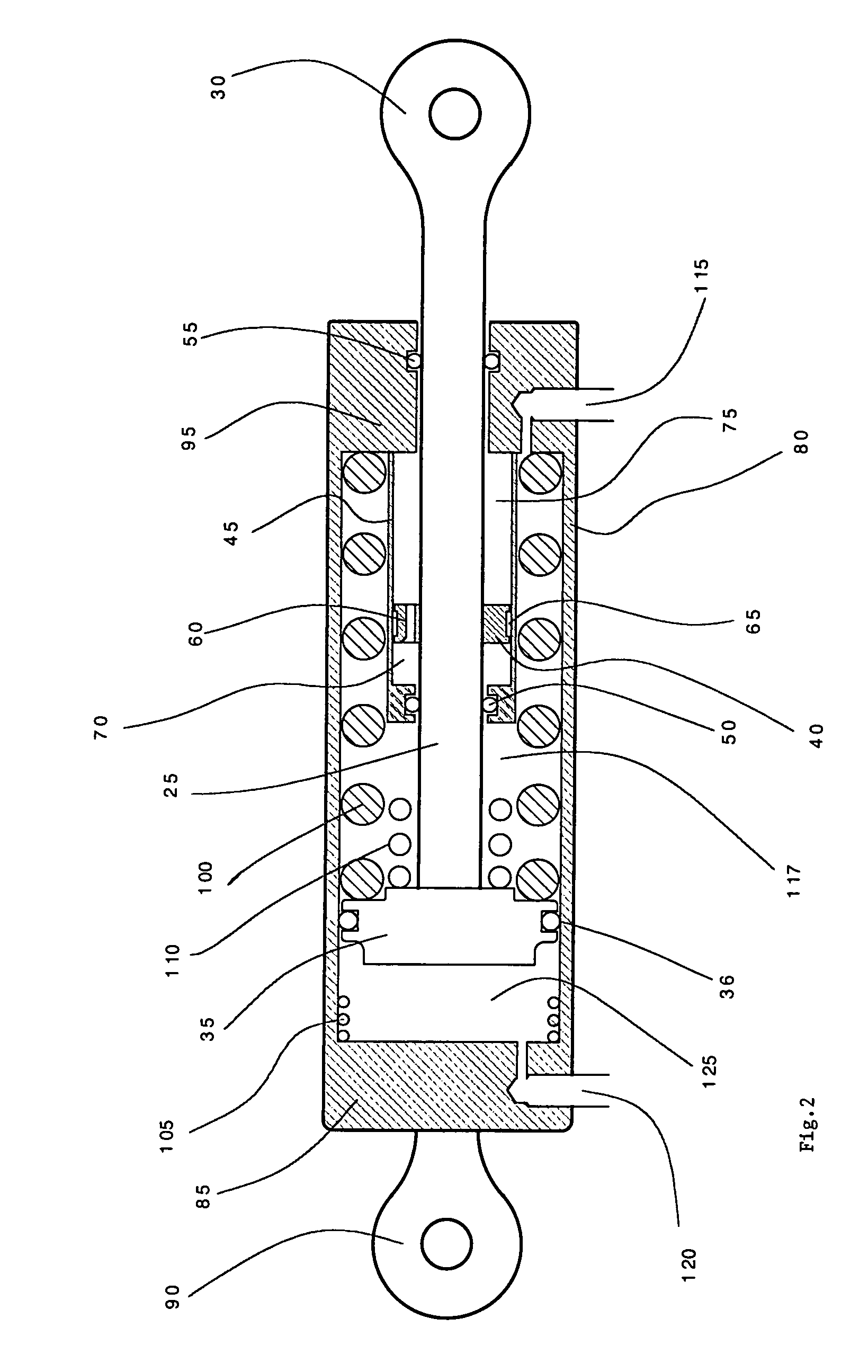
[0015]FIG. 2 shows the internal construction of the suspension unit 1, which comprises a shaft 25 having a connection fitting 30 at one end, which is a means for attaching the suspension unit 1 to a suspension mount 3 of the motorcycle 2. The suspension mount 3 may be any number of methods known to those skilled in the art. A clevis is typically used, but a stud post or other means may work just as well. It may also be noted that the suspension unit 1 works equally well with the connection fitting 30 attached to eit...


PUM


Abstract

A suspension unit used in a pull type shock application is disclosed, whereby a main shaft passes completely through a damping fluid so that the shock absorber fluid is not compressed when the shock shaft is displaced. The shaft also acts on a compression spring by an additional piston on the shaft. A cylindrical outer housing provides two distinct air chambers. The pressurization of these air chambers alters the spring rate, preload of the suspension, and vehicle ride height.

Description


Claims


Application Information

Patent Timeline
Owner VINCENZO F COSTA
Why Eureka
Try Eureka