Temporary adjustable support brace

a technology of support braces and adjustable brackets, which is applied in the direction of building structures, building materials handling, construction, etc., can solve the problems of imposing height limitations, affecting the work efficiency of construction workers, and increasing the labor intensity of existing support systems used in icf tall wall construction

Inactive Publication Date: 2010-02-18
SORICH GEORGE RICHARD
View PDF42 Cites 11 Cited by
  • Summary
  • Abstract
  • Description
  • Claims
  • Application Information

AI Technical Summary

Problems solved by technology

Existing bracing systems used in ICF tall wall construction become much more labor intensive as the height of the wall increases {such as when the ICF is used to construct a wall of greater than 12 feet in height).
The disadvantages of this type of alignment system for tall walls include height limitations imposed by the length of the channel 120, and the loads of both scaffold planking and construction crew are part of the formed wall structure.
As shown in FIG. 3, this system does solve the height limitations of other systems, however it is a very slow and labor intensive system and method for tall wall construction.

Method used


Image

  • Temporary adjustable support brace
  • Temporary adjustable support brace
  • Temporary adjustable support brace

Examples


Embodiment Construction

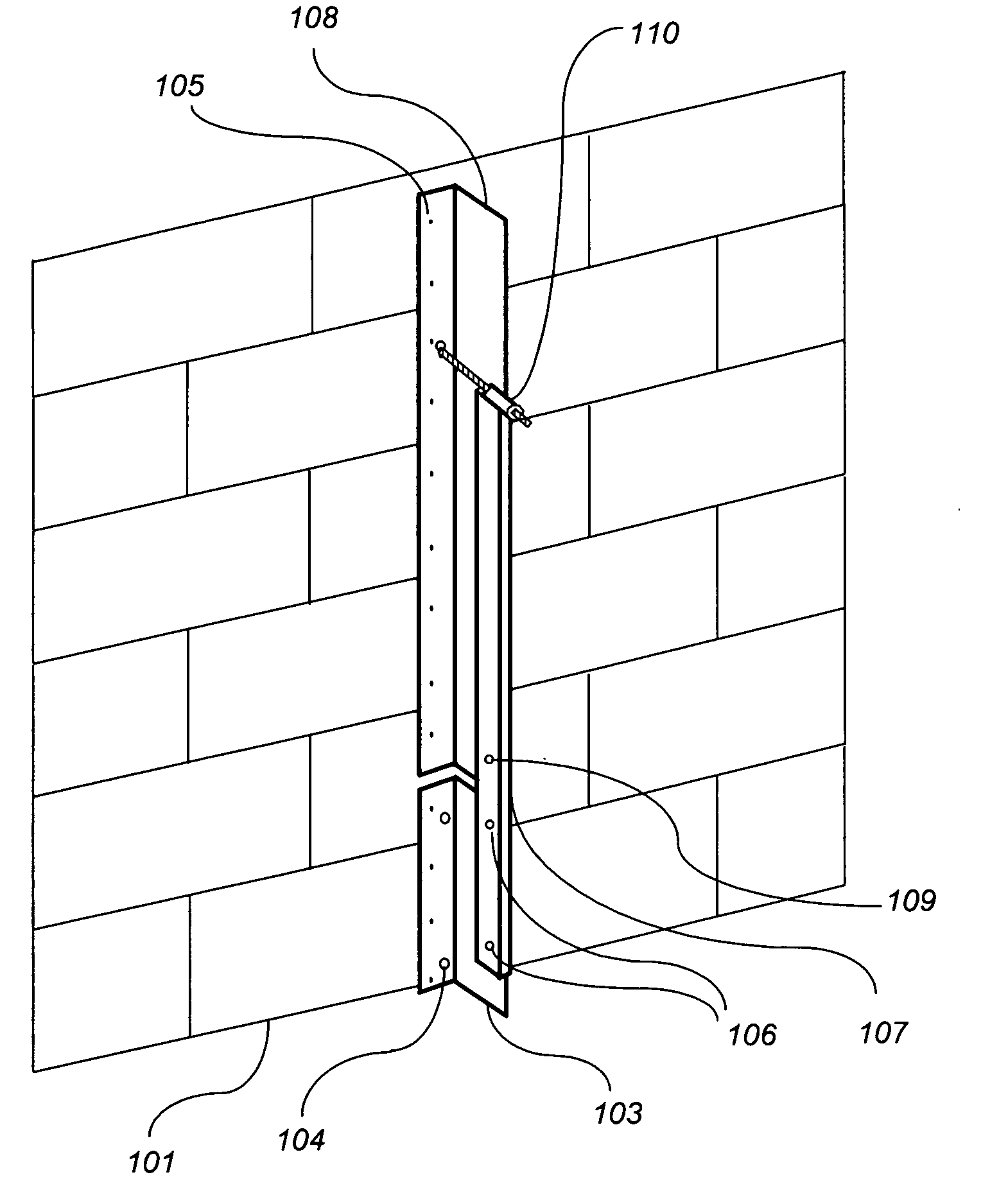
[0011]In the first aspect of the invention, as shown in FIG. 3 a bracing member 103 is disposed vertically and adjacent to the outside face of the first two rows of insulating panel forms 101 with at least one removable horizontal assembly 104 that passes thru the foam panel and will be imbedded in the poured concrete. Prior to placement of the poured concrete the vertical member 103 is temporarily attached to the bridging member end plates 104 of the insulated forms using screws. Typically the first two rows of ICF insulating panel forms are at ground level and therefore vertically plumbed using standard methods for concrete walls. A pourable concrete is then placed within and to the top of the first two rows of the insulating panel forms.

[0012]The next few rows of insulating panel forms are set in place above the lower rows. As shown in FIG. 4 a rigid vertical brace 107 is attached to the lower vertical member 103 at the location 106. The upper vertical member 108 is then attached...


PUM


Abstract

A system and method for securing an insulated concrete wall to keep the wall straight and plumb during construction, independent of any other bracing structure or scaffolding frame. The system uses the lower previously constructed section of the wall as a secure anchoring base for the continued construction of the wall. The system uses a member that is vertically placed and attached against the insulated form wall with at least one securing extension that passes thru the foam panel and into the cavity of the wall before concrete is placed within the wall cavity. After concrete is placed in the lower section and additional rows of insulated forms are placed on top of the lower wall, a vertical brace is attached to the lower vertical member so that it extends above the lower poured section of the wall. A vertical upper member is then attached to the upper section of the insulated form wall in proper alignment with the vertical brace. A securing adjustment device is attached to the upper member and the brace allowing for the upper section of the formed wall to be properly aligned and plumbed. This system and method is now repeated with the upper section of the formed wall to become the lower section of the formed wall. The system is repeated until the final desired wall height is reached.

Description

BACKGROUND[0001]1. Field of the Invention[0002]This invention relates generally to insulated concrete form (ICF) wall bracing, and more particularly to a system and method for bracing and aligning an insulated concrete wall form.[0003]2. Prior Art[0004]Conventional building construction utilizes concrete walls that are normally produced by constructing form walls, pouring concrete into the space between the walls and, upon setting of the concrete, removing the form walls. A conventional concrete form wall is disclosed in U.S. Pat. No. 4,333,289 to Strickland. The form wall includes a pair of spaced opposed panels made from plywood and defining therebetween a space into which fluid concrete is poured in forming the wall. Horizontally spaced vertical stiffeners or strongbacks are provided outwardly of each plywood panel to provide major strengthening for the panel support structure. Elongated beams or walers are also provided to extend horizontally along the outer side of each panel. ...

Claims


Application Information

Patent Timeline
Patent Type & Authority Applications(United States)
IPC IPC(8): E04G21/26
CPCE04G21/26
Inventor SORICH, GEORGE RICHARD
Owner SORICH GEORGE RICHARD
Why Eureka
Try Eureka