Cement mixing device for land photovoltaic power station construction

A technology of mixing device and photovoltaic power station, applied in cement mixing device, unloading device, clay preparation device, etc., can solve the problems of low mixing efficiency, reduction of construction speed of land photovoltaic power station, time-consuming and labor-intensive, etc.

Inactive Publication Date: 2017-08-29
王志强
View PDF0 Cites 17 Cited by
  • Summary
  • Abstract
  • Description
  • Claims
  • Application Information

AI Technical Summary

Problems solved by technology

[0005] In order to overcome the shortcomings of manual mixing of cement, which is time-consuming and labor-intensive and has low mixing efficiency, which will reduce the construction speed of land photovoltaic power plants, and the existing cement mixing device has poor mixing effect, the technic

Method used


Image

  • Cement mixing device for land photovoltaic power station construction
  • Cement mixing device for land photovoltaic power station construction
  • Cement mixing device for land photovoltaic power station construction

Examples


Embodiment 1

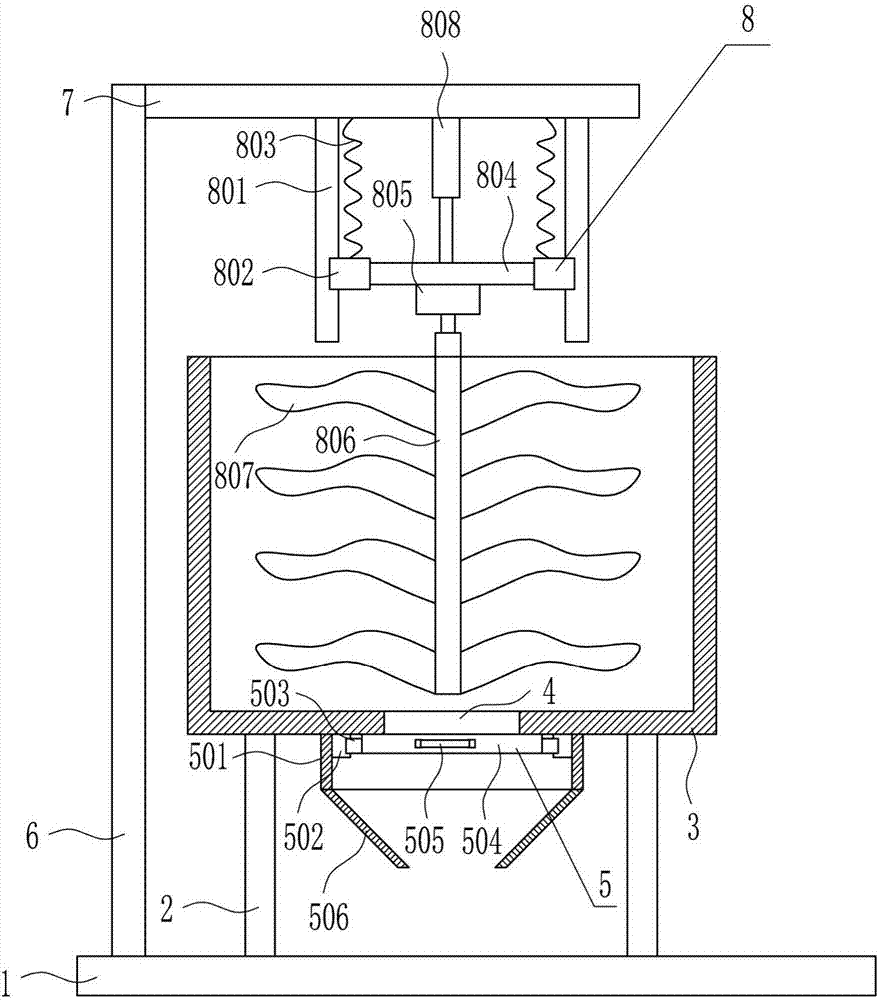
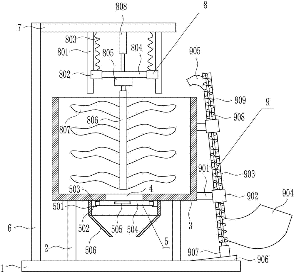
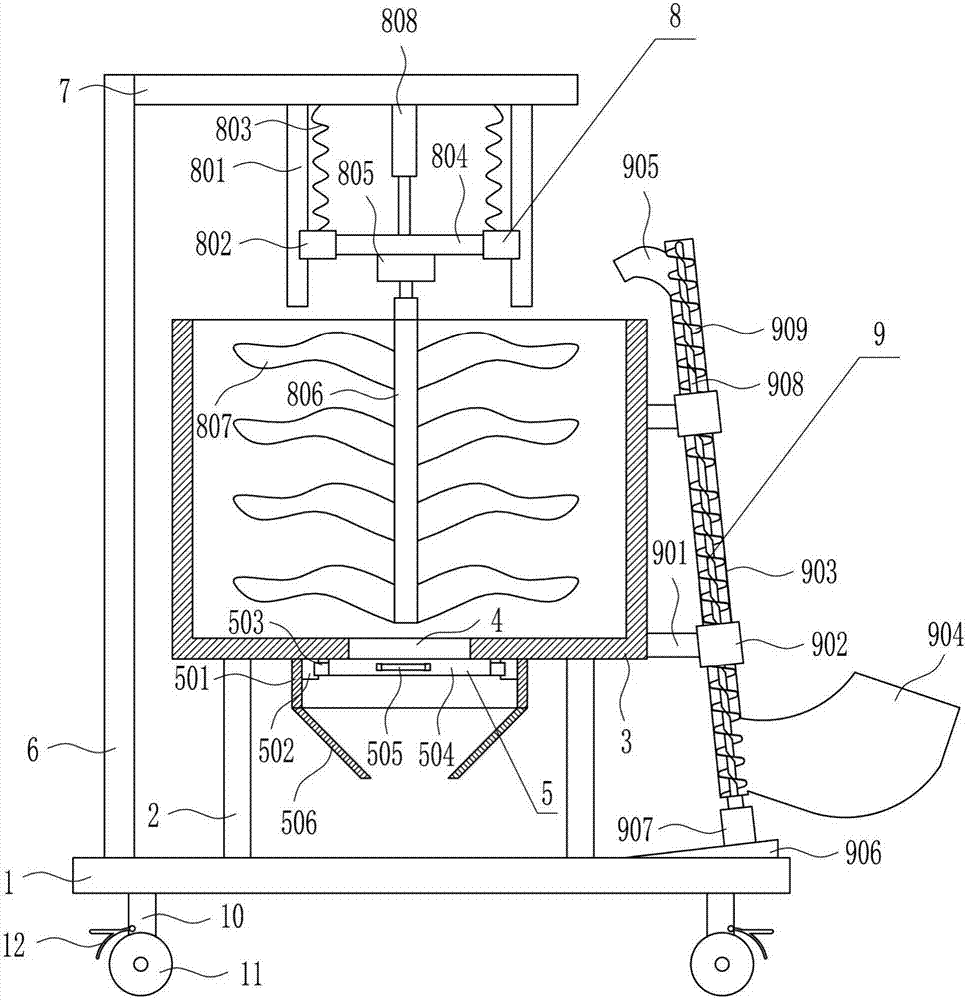
[0027] A cement mixing device for the construction of a land photovoltaic power station, such as Figure 1-3 As shown, it includes a bottom plate 1, a support plate 2, a mixing tank 3, a feeding device 5, a vertical plate 6, a top plate 7 and a stirring device 8. The top of the bottom plate 1 is provided with two support plates 2, and the two support plates 2 are about Symmetrical, the tops of the two support plates 2 are connected with a mixing tank 3 by bolts, the middle of the bottom of the mixing tank 3 is provided with a feeding port 4, and the bottom of the mixing tank 3 below the feeding port 4 is provided with a feeding device 5, and the stirring The top of the bottom plate 1 on the left side of the bucket 3 is connected with a vertical plate 6 by bolts, and the right side of the vertical plate 6 is connected with a top plate 7 by bolts. The bottom of the top plate 7 is provided with a stirring device 8, and the stirring parts of the stirring device 8 are located in the...

Embodiment 2

[0029] A cement mixing device for the construction of a land photovoltaic power station, such as Figure 1-3 As shown, it includes a bottom plate 1, a support plate 2, a mixing tank 3, a feeding device 5, a vertical plate 6, a top plate 7 and a stirring device 8. The top of the bottom plate 1 is provided with two support plates 2, and the two support plates 2 are about Symmetrical, the tops of the two support plates 2 are connected with a mixing tank 3 by bolts, the middle of the bottom of the mixing tank 3 is provided with a feeding port 4, and the bottom of the mixing tank 3 below the feeding port 4 is provided with a feeding device 5, and the stirring The top of the bottom plate 1 on the left side of the bucket 3 is connected with a vertical plate 6 by bolts, and the right side of the vertical plate 6 is connected with a top plate 7 by bolts. The bottom of the top plate 7 is provided with a stirring device 8, and the stirring parts of the stirring device 8 are located in the...

Embodiment 3

[0032] A cement mixing device for the construction of a land photovoltaic power station, such as Figure 1-3 As shown, it includes a bottom plate 1, a support plate 2, a mixing tank 3, a feeding device 5, a vertical plate 6, a top plate 7 and a stirring device 8. The top of the bottom plate 1 is provided with two support plates 2, and the two support plates 2 are about Symmetrical, the tops of the two support plates 2 are connected with a mixing tank 3 by bolts, the middle of the bottom of the mixing tank 3 is provided with a feeding port 4, and the bottom of the mixing tank 3 below the feeding port 4 is provided with a feeding device 5, and the stirring The top of the bottom plate 1 on the left side of the bucket 3 is connected with a vertical plate 6 by bolts, and the right side of the vertical plate 6 is connected with a top plate 7 by bolts. The bottom of the top plate 7 is provided with a stirring device 8, and the stirring parts of the stirring device 8 are located in the...


PUM


Abstract

The invention relates to a device for land photovoltaic power station construction, in particular to a cement mixing device for land photovoltaic power station construction. The cement mixing device for land photovoltaic power station construction can save time and labor, improve mixing efficiency and the mixing effect and increase the construction speed of a photovoltaic power station and is easy to operate. The cement mixing device for land photovoltaic power station construction comprises a base plate and the like. Two supporting plates are arranged at the top of the base plate and are in bilateral symmetry, a mixing tank is connected between the two supporting plates through bolts, and a discharging port is formed in the middle of the bottom of the mixing tank; and a discharging unit is arranged at the part, below the discharging port, of the bottom of the mixing tank, and a vertical plate is connected to the part, on the left side of the mixing tank, of the top of the base plate through bolts. According to the cement mixing device for land photovoltaic power station construction, cement is stirred by means of the method that mixing blades are rotated and vertically moved at the same time.

Description

technical field [0001] The invention relates to a device for building a land photovoltaic power station, in particular to a cement mixing device for building a land photovoltaic power station. Background technique [0002] Photovoltaic power station refers to a photovoltaic power generation system that uses solar energy and uses special materials such as crystalline silicon panels, inverters and other electronic components to connect to the grid and transmit power to the grid. Photovoltaic power plants are currently the green power development energy projects that are most encouraged by the state. It can be divided into independent power generation system with battery and grid-connected power generation system without battery. Solar power generation is divided into photothermal power generation and photovoltaic power generation. The commercialization of solar power in the current period refers to solar photovoltaic power generation. [0003] In order to make the position ...

Claims


Application Information

Patent Timeline
IPC IPC(8): B28C5/16B28C5/08B28C7/10B28C7/16
CPCB28C5/16B28C5/0831B28C5/0893B28C7/10B28C7/16
Inventor 王志强
Owner 王志强
Why Eureka
Try Eureka