

Hydraulic self-moving steel mould trolley and construction method thereof
A technology of steel formwork trolley and construction method, which is applied in earthwork drilling, wellbore lining, tunnel lining, etc. It can solve the problems that concrete construction defects cannot be dealt with in time, small curvature turning cannot be realized, installation and removal are inconvenient, etc. Achieve the effects of improving construction accuracy and construction speed, ensuring the quality of steel bar binding, and large demoulding space
- Summary
- Abstract
- Description
- Claims
- Application Information
AI Technical Summary
Problems solved by technology
Method used
Image

Examples
Embodiment Construction
[0054]In the following description, numerous specific details are set forth in order to provide a thorough understanding of the present invention. However, the present invention can be implemented in many other ways different from those described here, and those skilled in the art can make similar extensions without violating the connotation of the present invention, so the present invention is not limited by the specific embodiments disclosed below.
[0055] In the following, specific embodiments of the present invention will be described in conjunction with the accompanying drawings.
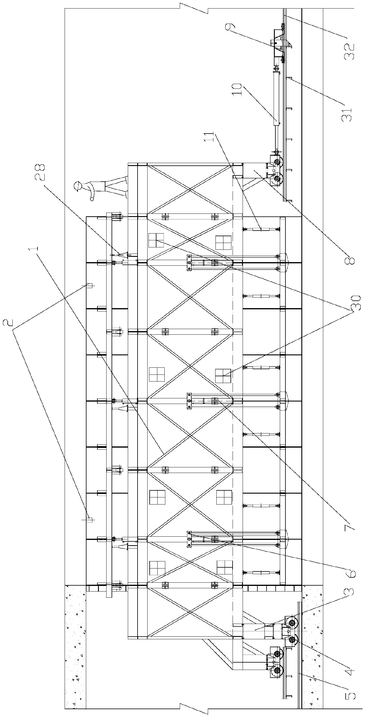
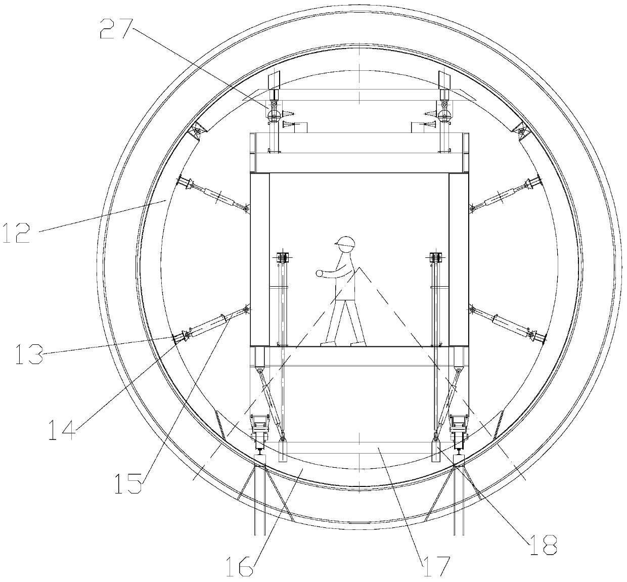
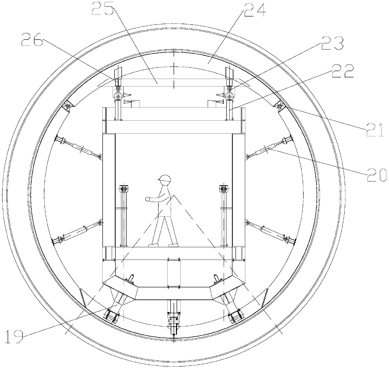
[0056] see Figures 1 to 4 As shown, the present invention provides a hydraulic self-moving steel formwork trolley and its construction method. The hydraulic self-moving steel formwork trolley can meet the construction requirements of the concrete lining of a full-section circular tunnel, including simple structure and convenient installation. , strong adaptability, the ability to demould the...
PUM
| Property | Measurement | Unit |
|---|---|---|
| Length | aaaaa | aaaaa |
Abstract
Description
Claims
Application Information