Hydraulic self-moving steel formwork trolley and its construction method

A steel form trolley, self-moving technology, which is used in earth-moving drilling, wellbore lining, tunnel lining and other directions, can solve the problems that concrete construction defects cannot be dealt with in time, small curvature turns cannot be realized, and manufacturing and installation costs are high. Achieve the effect of improving construction accuracy and construction speed, ensuring the quality of steel bar binding, and fast and timely processing

Active Publication Date: 2015-08-19
CHINA THREE GORGES CORPORATION +1
View PDF8 Cites 2 Cited by
  • Summary
  • Abstract
  • Description
  • Claims
  • Application Information

AI Technical Summary

Problems solved by technology

[0002] At present, the concrete lining of full-section circular tunnels usually uses needle-beam steel formwork trolleys. The needle-beam steel formwork trolleys in the prior art can not only complete the concrete lining of full-section circular tunnels, but also pass through the arc section of the tunnel safely and quickly. However, the prominent disadvantages of the needle-beam type steel formwork trolley in the prior art are: first, the heavy trolley, long needle beam, inconvenient installation and removal; second, relatively high manufacturing and installation costs, and it is difficult to amortize the cost for short-length tunnels , the larger the cross-section, the higher the amortization cost; the third is that the adaptability is relatively poor, and it is difficult for the trolley to turn in the cave, and it is impossible to turn the small curvature; the fourth is that the lining concrete can only be demoulded after it is strengthened, and the concrete construction defect Cannot be dealt with in time, especially the bottom defect can only be repaired after the trolley is moved

Method used


Image

  • Hydraulic self-moving steel formwork trolley and its construction method
  • Hydraulic self-moving steel formwork trolley and its construction method
  • Hydraulic self-moving steel formwork trolley and its construction method

Examples


Embodiment Construction

[0053]In the following description, numerous specific details are set forth in order to provide a thorough understanding of the present invention. However, the present invention can be implemented in many other ways different from those described here, and those skilled in the art can make similar extensions without violating the connotation of the present invention, so the present invention is not limited by the specific embodiments disclosed below.

[0054] In the following, specific embodiments of the present invention will be described in conjunction with the accompanying drawings.

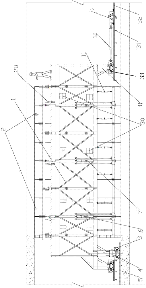
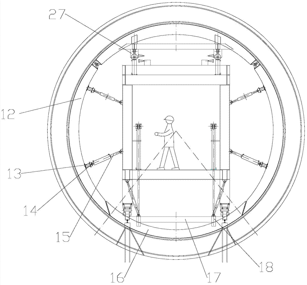
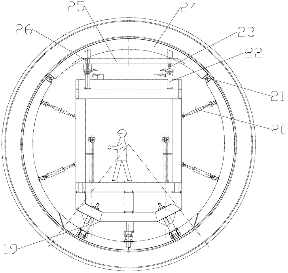
[0055] see Figures 1 to 4 As shown, the present invention provides a hydraulic self-moving steel formwork trolley and its construction method. The hydraulic self-moving steel formwork trolley can meet the construction requirements of the concrete lining of a full-section circular tunnel, including simple structure and convenient installation. , strong adaptability, the ability to demould the...


PUM

PropertyMeasurementUnit
lengthaaaaaaaaaa

Abstract

The invention relates to a hydraulic self-moving steel mould trolley and a construction method of the hydraulic self-moving steel mould trolley. The hydraulic self-moving steel mould trolley is used for full-section circular tunnel concrete lining construction. The hydraulic self-moving steel mould trolley comprises a trolley moving device, a trolley structural frame, a steel structure combination formwork and a hydraulic control device, the trolley structural frame is arranged on the trolley moving device, the trolley structural frame is movably connected with the trolley moving device, the steel structure combination formwork is arranged in the trolley structural frame, the steel structure combination formwork is hinged to the trolley structural frame, and the hydraulic control device is used for controlling the hydraulic self-moving type steel mould trolley. The hydraulic self-moving steel mould trolley is simple in structure, convenient to install, strong in adaptability and capable of carrying out demoulding on concrete at the bottom of the tunnel at first and repairing concrete construction defects in time.

Description

technical field [0001] The invention relates to the field of operating devices for tunnel concrete lining, in particular to a hydraulic self-moving steel mold trolley for constructing concrete lining of a full-section circular tunnel and a construction method thereof. Background technique [0002] At present, the concrete lining of full-section circular tunnels usually uses needle-beam steel formwork trolleys. The needle-beam steel formwork trolleys in the prior art can not only complete the concrete lining of full-section circular tunnels, but also pass through the arc section of the tunnel safely and quickly. However, the prominent disadvantages of the needle-beam type steel formwork trolley in the prior art are: first, the heavy trolley, long needle beam, inconvenient installation and removal; second, relatively high manufacturing and installation costs, and it is difficult to amortize the cost for short-length tunnels , the larger the cross-section, the higher the amorti...

Claims


Application Information

Patent Timeline
Patent Type & Authority Patents(China)
IPC IPC(8): E21D11/10
Inventor 王宗敏祁雪春陈育权李凯章琦云刘纯王江杨志才陈亮杨岳林
Owner CHINA THREE GORGES CORPORATION
Why Eureka
Try Eureka