
Spray can assembly for painting golf holes

Inactive Publication Date: 2008-12-04
SCHLEICHER KURT
View PDF1 Cites 12 Cited by
  • Summary
  • Abstract
  • Description
  • Claims
  • Application Information

AI Technical Summary

Benefits of technology

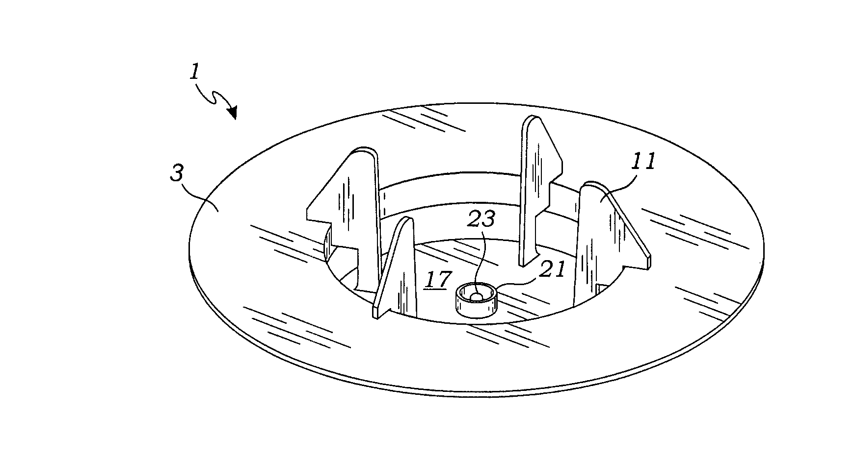
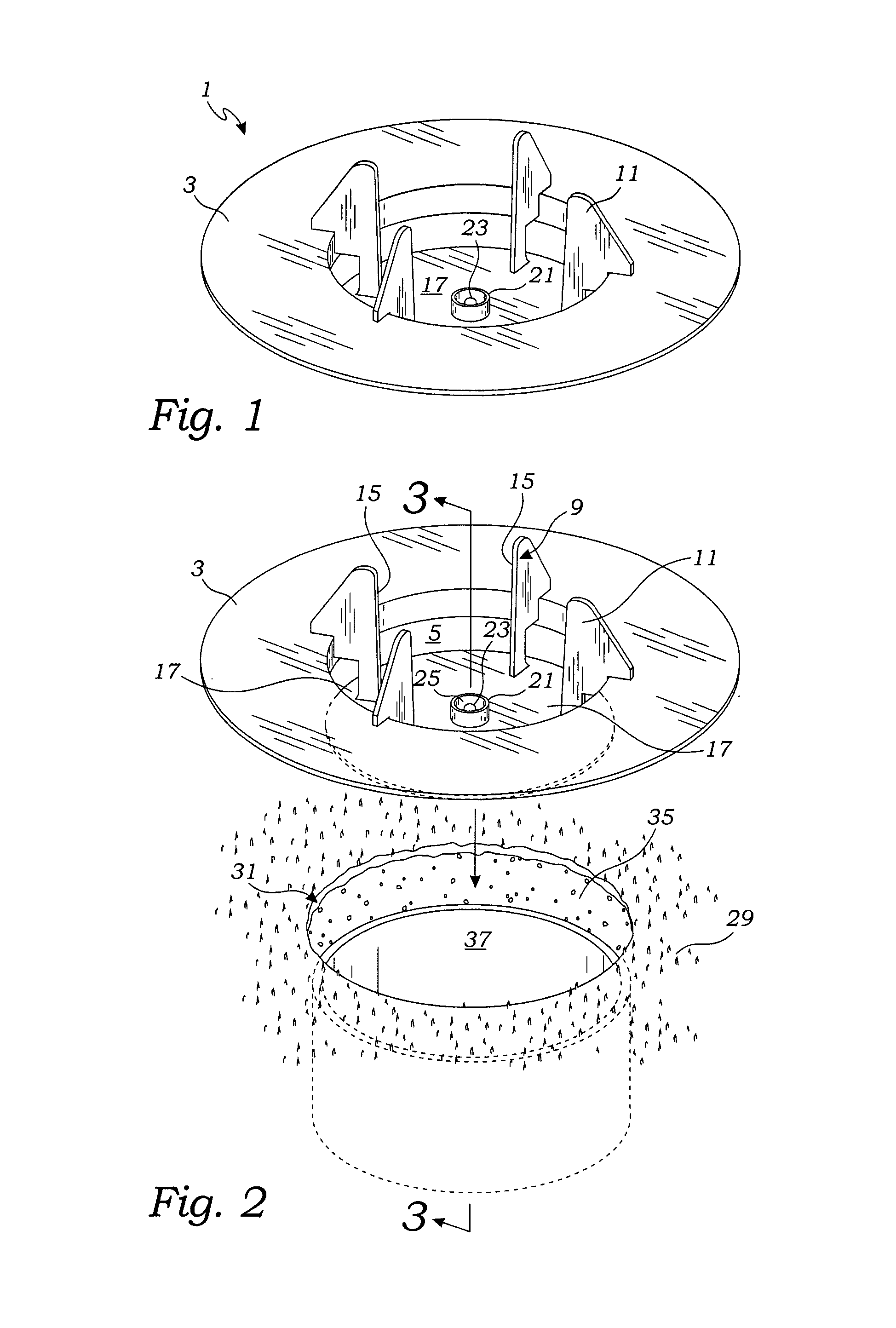
[0011]The spray paint can holder of the present invention includes a base, preferably in the form of a cylindrical disk, which has a central circular opening defining a central axis. The spray paint can holder further includes a plurality of arms which project inwardly and downwardly to form a receptacle for holding an inverted spray can including its valve assembly. The spray paint can holder may include any number of arms. However, a preferred construction includes four arms spaced equal distance about the periphery of the base so as to provide sufficient structure for adequately holding the spray paint can while not providing too much structure which would undesirably block the spray of paint.
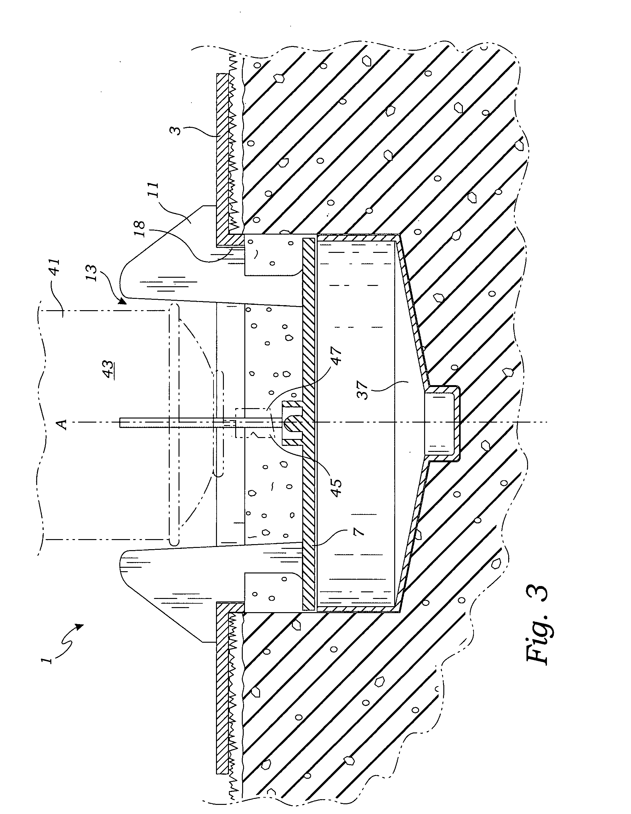
[0013]In a preferred embodiment, the spray paint can holder further includes a cup which is positioned on the plate's center. The cup includes a circular sidewall forming a central cavity which is sized to capture the nozzle button of a spray can. A projection in the form of a nub projects upwardly from the center of the cup for engaging a spray can nozzle when the spray can is placed in an inverted position within the receptacle. The apparatus may include a skirt which extends downwardly from the base opening to prevent paint from being applied to grass around the golf hole.
[0015]It is an additional object of the invention to provide an apparatus which provides a uniform coating and uniform masking for creating a golf hole wherein the paint has a uniform thickness within its interior edge.
[0016]It is still a further object of the invention to provide an improved apparatus for holding a golf can which does not require making any alterations to the push button nozzle of typical spray cans.

Problems solved by technology

However, a preferred construction includes four arms spaced equal distance about the periphery of the base so as to provide sufficient structure for adequately holding the spray paint can while not providing too much structure which would undesirably block the spray of paint.

Method used


Image

  • Spray can assembly for painting golf holes
  • Spray can assembly for painting golf holes
  • Spray can assembly for painting golf holes

Examples


Embodiment Construction

[0022]While the present invention is susceptible of embodiments in various forms, as shown in the drawings, hereinafter will be described the presently preferred embodiments of the invention with the understanding that the present disclosure is to be considered as an exemplification of the invention, and it is not intended to limit the invention to the specific embodiments illustrated.

[0023]With reference to FIGS. 1-4, the apparatus 1 for positioning a spray paint can 41 is intended for use in providing a uniform strip of paint around the interior rim of a golf hole. As best seen in FIG. 2, a golf green 21 includes a circular golf hole 31 formed into the grassy surface 3 of a golf green. With the introduction of a cup 37 into the bottom interior of the golf hole, a dirt and grass periphery 35 is created which would desirably be painted white so as to be visually seen by golfers at a greater distance. The positioning apparatus 1 includes a substantially planar base 3 which may take v...


PUM


Abstract

A spray paint can positioning apparatus is provided for painting the interior of a golf hole. The positioning apparatus includes a planar base having a central opening and a plurality of downwardly extending arms forming a receptacle for holding a spray paint can. Each of the arms engage a circular masking plate having a diameter substantially the same as the diameter of a golf hole. A cup having a circular sidewall is formed on the top of the masking plate for receipt of the push button from an inverted spray paint can. Located in the middle of the cup, a projection is positioned to engage and depress the push button of a spray paint can. The cup is sized to prevent lateral movement of the spray can push button and the masking plate provides a uniform width of paint around the interior periphery of a golf hole.

Description

BACKGROUND OF THE INVENTION[0001]The present invention relates to the preparation of golf holes on a golf course. More particularly, the present invention relates to devices for creating a white paint to the walls of golf hole for providing greater visibility to golfers.[0002]A golf hole is typically formed in a golf green by removing a cylindrical section of grass and underlying dirt using a specialized hole cutting tool. The cutting tool is positioned in a desired location after which a greenskeeper tries to maintain the cutter perpendicular to the green's surface while forcing the cutter into the ground. The cutter inserts the cutting tool to a desired depth after which the cutting tool is removed, thereby removing a plug of earth and grass and leaving a hole in the green. If a golf hole has previously been formed within the same green, the greenskeeper will typically place the removed plug of earth and grass and place it into the previously formed golf hole. A plastic cup, which...

Claims


Application Information

Patent Timeline
Patent Type & Authority Applications(United States)
IPC IPC(8): A62C13/62
CPCA63B57/0056A63B57/40A63B57/357
Inventor SCHLEICHER, KURT
Owner SCHLEICHER KURT
Learn More