Disposable dental prophylaxis apparatus capable of discharging predetermined amount of dentifrice material therefrom

a dental prophylaxis and discharging technology, applied in the field of discharging dental prophylaxis equipment, can solve the problems of not being really made or used, not sufficiently considering the supply and demand laws that should be satisfied from the manufacturing process to the practical use process, and failing to meet some practical conditions. , to achieve the effect of inexpensive costs

Inactive Publication Date: 2009-03-31
LEE KWANG S +1
View PDF5 Cites 13 Cited by
  • Summary
  • Abstract
  • Description
  • Claims
  • Application Information

AI Technical Summary

Benefits of technology

[0021]Accordingly, the present invention has been made in view of the above-mentioned problems occurring in the prior art, and it is an object of the present invention to provide a disposable dental prophylaxis apparatus capable of discharging a predetermined amount of dentifrice material therefrom that is configured to have an adequate structure to the sizes of general disposable dental prophylaxis devices widely used in the art, thereby enabling the product to be made in great quantities and at inexpensive costs and providing many conveniences to both of dentists and patients.
[0022]It is another object of the present invention to provide a disposable dental prophylaxis apparatus capable of discharging a predetermined amount of dentifrice material therefrom that is compatible to existing hand motors, without changing any new one, such that when dentists who use conventional disposable dental prophylaxis devices employ the disposable dental prophylaxis apparatus of the present invention, they can utilize it skillfully, without feeling any inconvenience while in use.
[0027]The wheel gear has a force stabilizing ring formed along the upper end periphery thereof for preventing the generation of shaking during rotation and a drain hole formed along the inside middle portion thereof for discharging the dentifrice material therefrom, the drain hole having a diameter of about 1.5 mm.
[0029]The joint gear has a vibration-absorbing groove adapted for absorbing the vibration generated from the extended portion thereof, a reinforcing shaft for preventing the generation of twisting thereon, and a plurality of force stabilizing rings for maintaining the concentric force generated while being rotated at a high speed.

Problems solved by technology

Unfortunately, the first prior art is well explained with the help of the drawings and description, but actually, it fails to satisfy some practical conditions such as the structural conditions in a manufacturing process, the cost conditions in a distributing process, and the physical operation principles in practical uses, such that the product is not really made or used at all in this related art up to now after this patent has been granted.
By the way, according to the first prior art, the ribbon type of conveyor is housed in the tiny space of the cartridge and further, the polishing paste is charged at the inside of the cartridge, which fails to sufficiently consider the supply and demand laws that should be satisfied from the manufacturing process to the practical use process.
In addition to the structural difficulties the first prior art has as mentioned above, it has the operational difficulties wherein the screw conveyor stops while the cartridge is being rotated, thereby discharging the polishing paste therefrom.
Physically, this is like the principle where an automobile starts at the state of being braked, and in this case, as a substantially strong force is applied to the inside of the cartridge, the conveyor becomes twisted, which makes it impossible to discharge the polishing paste therefrom.
Furthermore, the rotating force is not transferred well by the application of the substantially strong force, which causes power braking such that the gears adapted to be in engagement with each other are abrasive to run idle.
For these reasons, it is found that the patent right of the first prior art is terminated, while not put into practical use.
However, according to the above-mentioned aspects of the second prior art, as the charged dentifrice material undesirably sticks to the shaft when the shaft is rotated, power braking severely occurs on a hand piece motor, which results in high heat generation on the hand piece motor.
In addition, as the shaft is rotated at the state of being buried into the dentifrice material, the rotating force of the shaft is not exerted well as if a boat is not advanced well by the application of high water pressure caused by the rotation of a screw under the water.
Thus, the prophylaxis cup that has to be rotated at a high speed is not really rotated rapidly, which loses its friction function against a patient's tooth.
Moreover, the second prior art is very complicated in its structure, which makes it hard to perform a mold-manufacturing process and an injection molding process, and specifically, even though all parts are made, they could not be assembled structurally with one another, such that no final product is made up to present.

Method used


Image

  • Disposable dental prophylaxis apparatus capable of discharging predetermined amount of dentifrice material therefrom
  • Disposable dental prophylaxis apparatus capable of discharging predetermined amount of dentifrice material therefrom
  • Disposable dental prophylaxis apparatus capable of discharging predetermined amount of dentifrice material therefrom

Examples


Embodiment Construction

[0059]Hereinafter, an explanation of a disposable dental prophylaxis apparatus capable of discharging a predetermined amount of dentifrice material therefrom according to the present invention will be given with reference to the attached drawings.

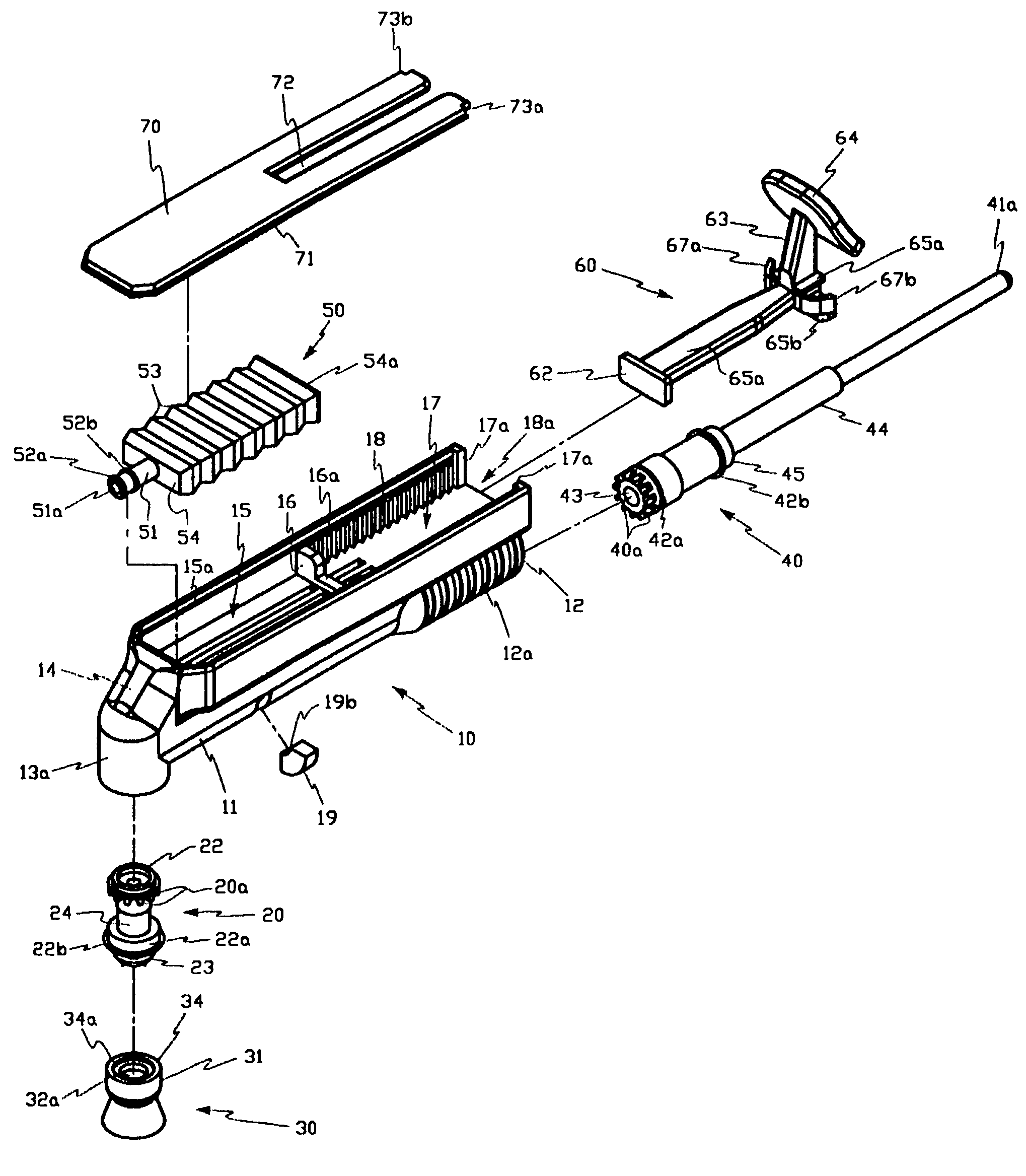
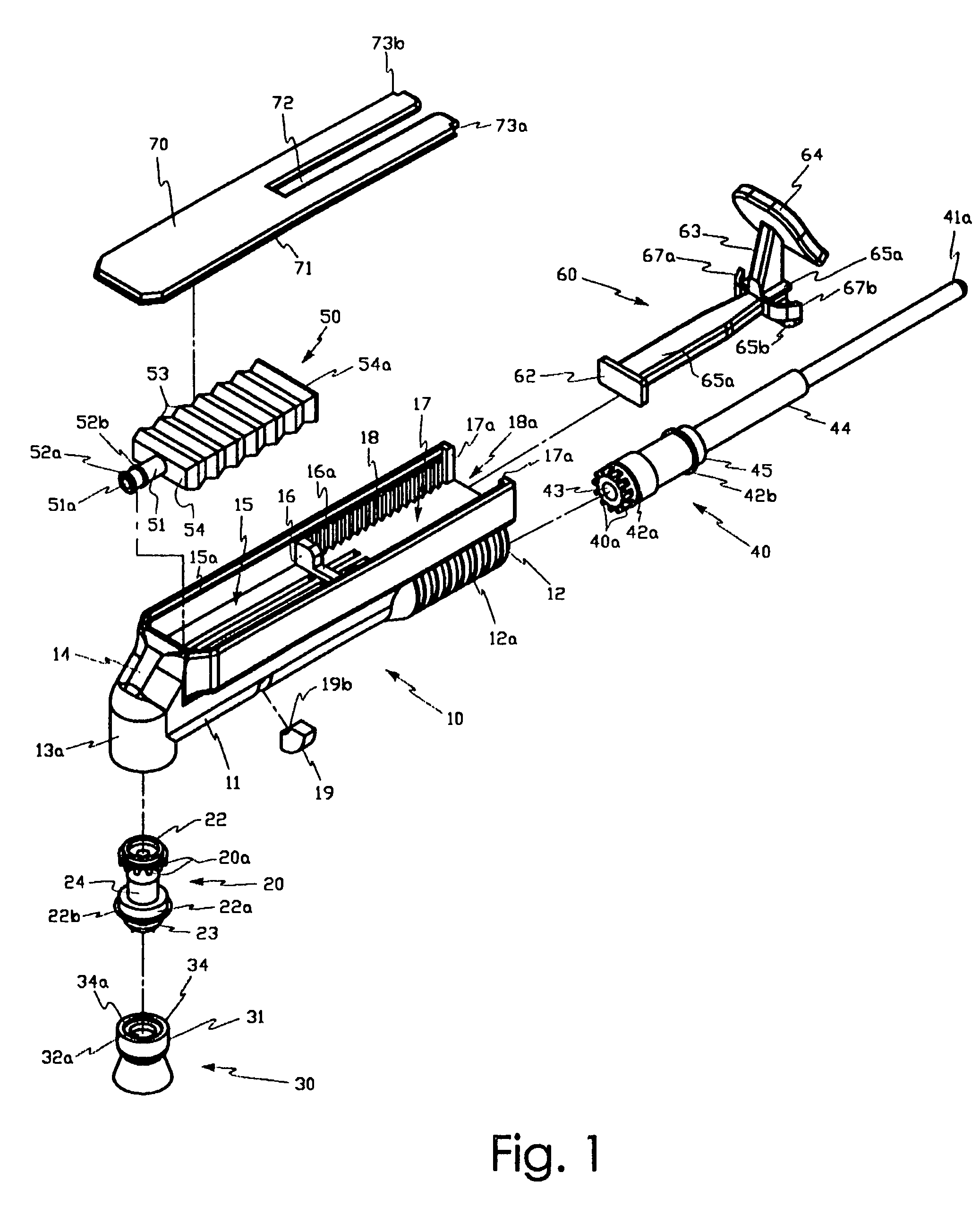
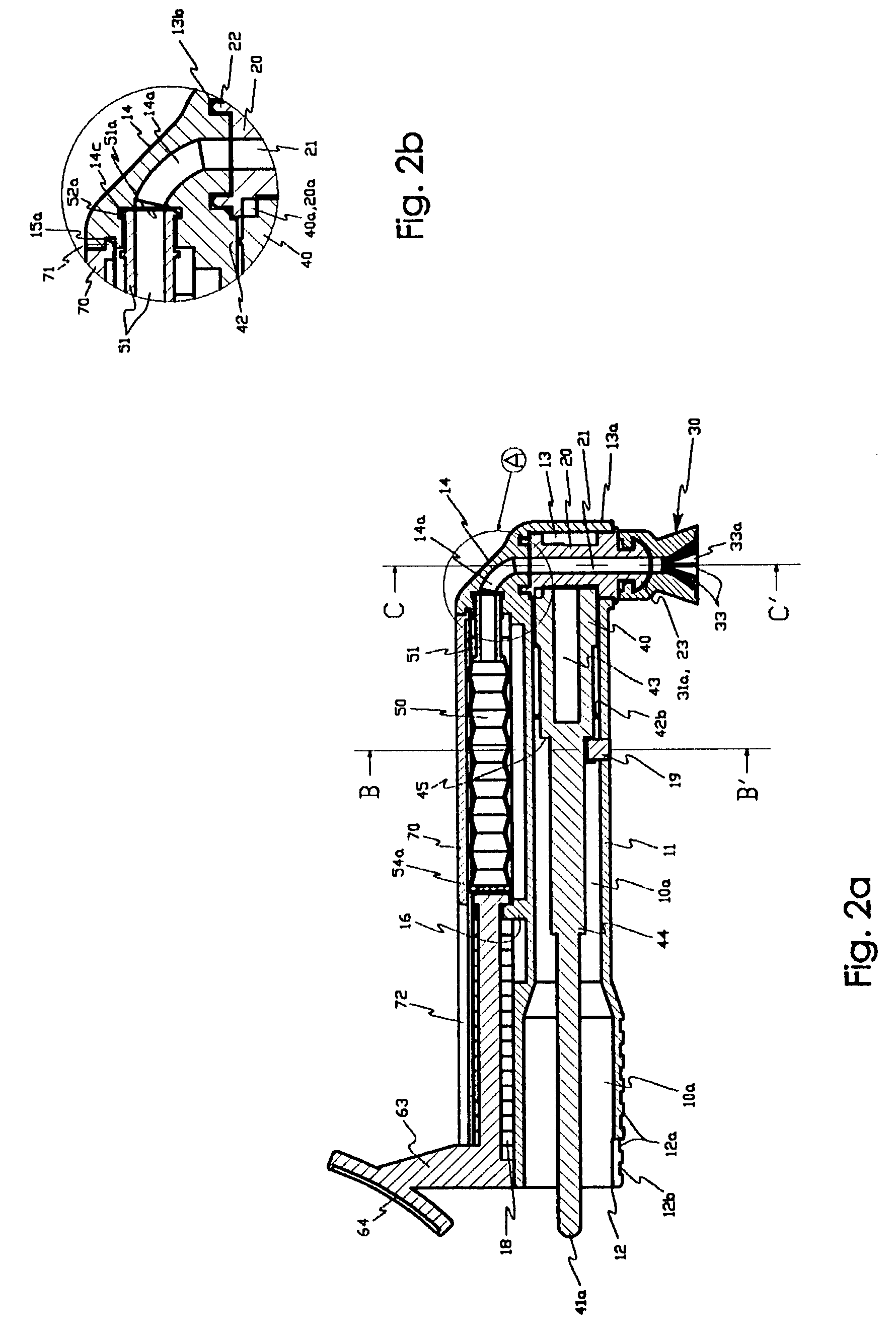
[0060]FIG. 1 is an exploded perspective view showing a disposable dental prophylaxis apparatus capable of discharging a predetermined amount of dentifrice material therefrom according to the present invention, FIG. 2a is a sectional view taken along the line of A-A′ of FIG. 10, FIG. 2b is an enlarged sectional view showing the parts in a circle ‘A’ of FIG. 2a, FIG. 3a is a sectional view showing a configuration of a housing of the disposable dental prophylaxis apparatus of the present invention, FIG. 3b is an enlarged sectional view showing the parts in a circle ‘A’ of FIG. 3a, FIG. 4 is a perspective view showing the assembled state of the disposable dental prophylaxis apparatus of the present invention, FIG. 5 is a bottom perspective view...


PUM


Abstract

The present invention relates to a hand tool used by dental professionals to polish a patient's tooth. The hand tool can be connected to a hand motor used to rotate a wheel cup with a plurality of grinding wings that rub against the patient's tooth as a predetermined amount of dentifrice material is discharged directly on the patient's tooth through a drain hole within the wheel cup. The dentifrice material is discharged from a tube that is assembled in the housing of the hand tool. The tube has a plurality of folds formed on the tube body in such a manner as to be folded by a given distance while being compressed to discharge the dentifrice material therefrom. The tube is compressed by a link with a push button that is guided in the forward direction as it is pushed by a finger.

Description

BACKGROUND OF THE INVENTION[0001]1. Field of the Invention[0002]The present invention relates to a disposable dental prophylaxis apparatus for use in scaling, grinding, or polishing the surface of teeth in dental fields, and more particularly, to a disposable dental prophylaxis apparatus that is capable of discharging a predetermined amount of dentifrice material therefrom such that dentists can effectively perform their desired dental operations with the dentifrice material discharged therefrom.[0003]2. Description of the Prior Art[0004]Presently, there have been provided various kinds of disposable dental prophylaxis devices in the art. For the full comprehension of this invention, two prior art inventions among them are suggested in this description, first of which is disclosed in U.S. Pat. No. 4,266,933 entitled ‘ROTARY DENTAL POLISHING APPARATUS’ and filed on May 12, 1981 (hereinafter, referred to as “first prior art”), and second of which is disclosed in U.S. Pat. No. 6,257,88...

Claims


Application Information

Patent Timeline
Patent Type & Authority Patents(United States)
IPC IPC(8): A61C5/04A61C1/12A61C3/03A61C3/06
CPCA61C17/005A61C17/227A61C17/00A61C19/00A61C17/22
Inventor LEE, KWANG S.GHIM, DUKE K.
Owner LEE KWANG S
Why Eureka
Try Eureka