
Vise clamp

a technology of vise clamp and clamping rod, which is applied in the field of vise clamp, can solve the problems of c-shaped vise clamp often loose, slow clamping speed, and inability to use the vise, and achieve the effect of stable and precise vise clamping

Inactive Publication Date: 2006-03-28
DARON TOOLS
View PDF5 Cites 46 Cited by
  • Summary
  • Abstract
  • Description
  • Claims
  • Application Information

AI Technical Summary

Benefits of technology

[0007]The primary objective of the present invention is to provide a stable and precise vise clamp.

Problems solved by technology

For example, in processing planks, a vise clamp can be moved to various positions as desired by a user, but a vise cannot.
For not including a retaining device, the C-shaped vise clamp often looses when subject to vibration.
Moreover, the movable jaw can only be moved by means of rotating the screw, the speed of clamping is slowed.
The smoothness of the operation is affected.
The time required for an effective clamping operation is short.
However, each grip collar contacts the rod at a limited spot.
Hence, the grip collars often make cuts in the rod.
Moreover, such cuts reduce the strength of the rod.
The limited spots provide inadequate grip so that the rod moves relative to the moving device when a large force is exerted on the first trigger for clamping.
Therefore, the performance of this conventional vise clamp is not satisfactory.

Method used


Image

  • Vise clamp
  • Vise clamp
  • Vise clamp

Examples


Embodiment Construction

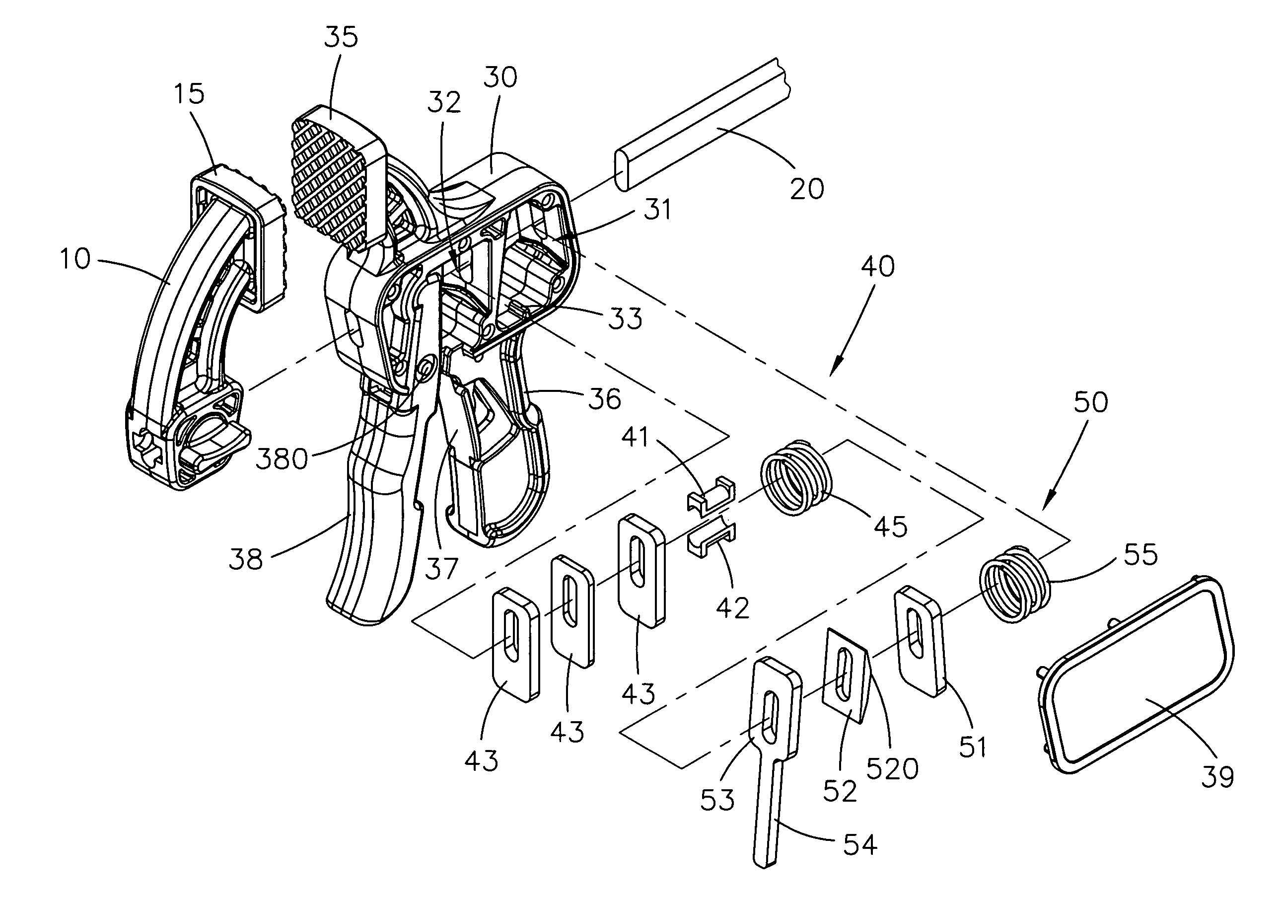
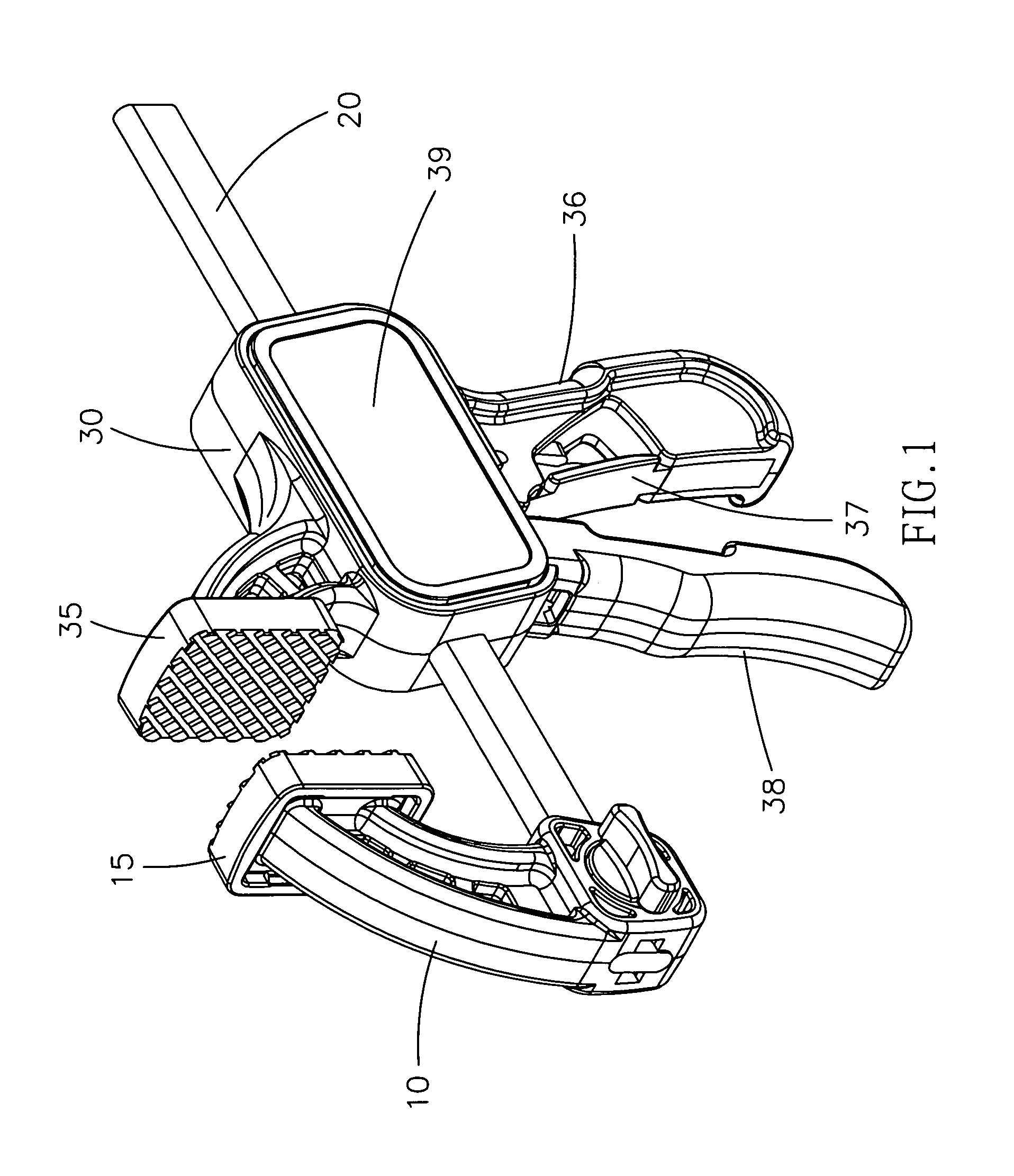
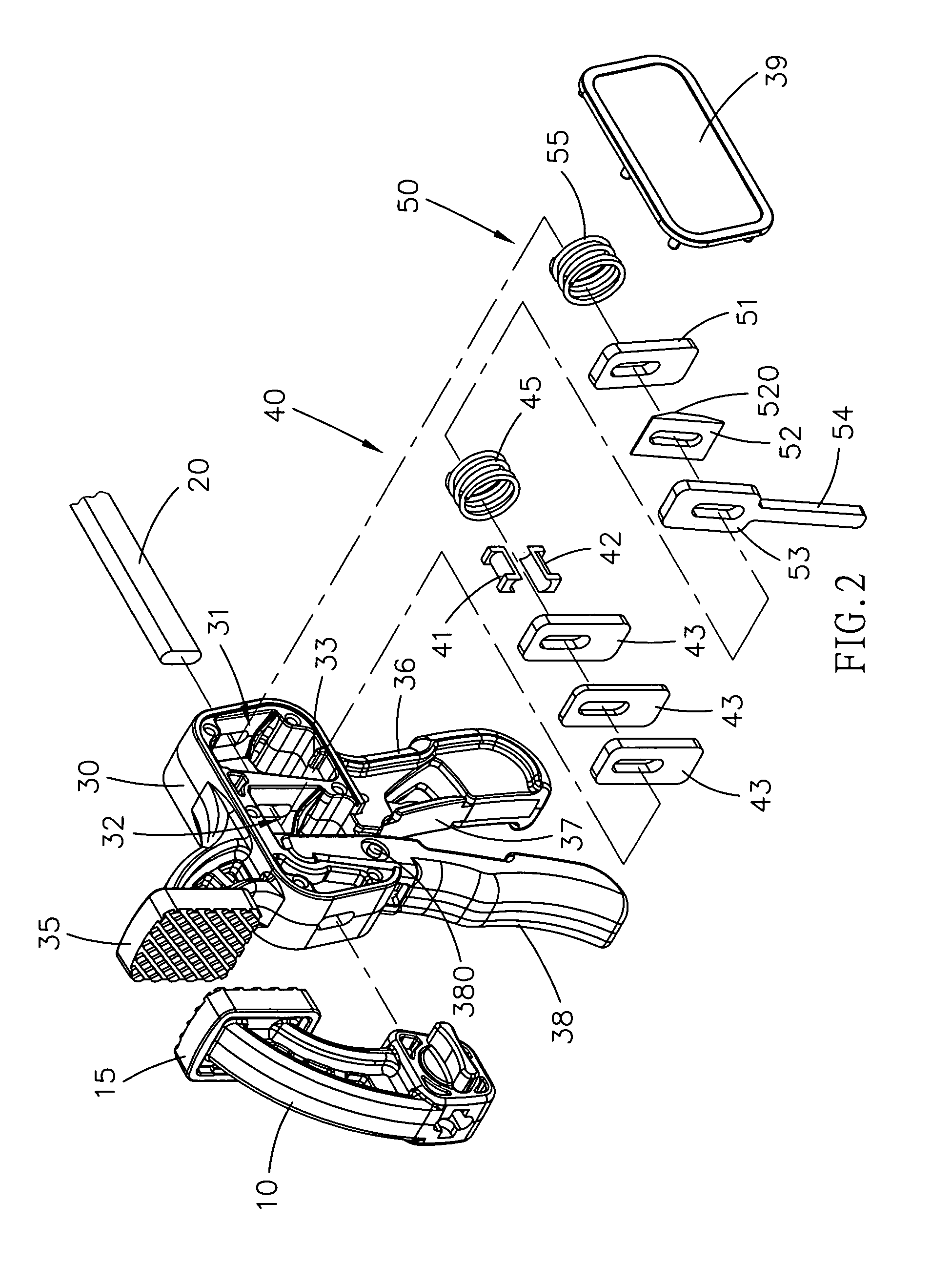
[0017]Referring to FIGS. 1 and 2, there is shown a vise clamp according to the preferred embodiment of the present invention. The vise clamp includes a movable jaw 10, a rod 20 and a stationary jaw 30. The movable jaw 10 includes a contact portion 15. The movable jaw 10 is secured to an end of the rod 20. The rod 20 is inserted through the stationary jaw 30 in which a moving device 40 and a retaining device 50 are installed. The stationary jaw 30 includes a contact portion 35 corresponding to the contact portion 15 of the movable jaw 10. The rod 20 can be moved relative to the stationary jaw 30 so that the contact portion 15 of the movable jaw 10 can be moved towards the contact portion 15 of the movable jaw 10 for clamping a workpiece and that the contact portion 15 of the movable jaw 10 can be moved from the contact portion 15 of the movable jaw 10 for releasing the workpiece.

[0018]Referring to FIGS. 1 through 4, the stationary jaw 30 defines a first chamber 31 in a rear portion i...


PUM


Abstract

There is disclosed a vise clamp for a stable and precise operation. The vise clamp includes movable and stationary jaws including corresponding contact portions. The movable jaw is secured to an end of a rod. The rod is inserted through the stationary jaw in a sliding manner. A first trigger is connected to the bottom of the stationary jaw. A second trigger is connected to a handle extended from the bottom of the stationary jaw. The first trigger is operable to drive a moving device in the stationary jaw. The second trigger is operable to drive a retaining device in the stationary jaw. The retaining device consists of grip collars around the rod. The moving device includes grip collars around the rod and two linings between the grip collars and the rod. Thus, the area of the contact of the moving device with the rod is large. Hence, the operation of the vise clamp is stable and precise, and the clamping force of the vise clamp is large.

Description

BACKGROUND OF INVENTION[0001]1. Field of Invention[0002]The present invention relates to a vise clamp and, more particularly, to a vise clamp that can be pushed in order to clamp, and the area of the contact of a movable jaw with a guide is increased in order to promote the stability and precision in its operation and its clamping force.[0003]2. Related Prior Art[0004]A vise clamp is primarily used in places where a vise cannot be used. For example, in processing planks, a vise clamp can be moved to various positions as desired by a user, but a vise cannot. A C-shaped vise clamp includes a body, a stationary jaw formed on the body, a screw installed on the body, and a movable jaw with a screw hole for receiving the screw. By means of rotating the screw, the movable jaw is moved up and down in order to clamp. For not including a retaining device, the C-shaped vise clamp often looses when subject to vibration. The following steps of the operation are thus affected. Moreover, the movab...

Claims


Application Information

Patent Timeline
IPC IPC(8): B25B5/02
CPCB25B5/068
Inventor LIN, CHIAN LING
Owner DARON TOOLS
Learn More