Method for detecting a moving object in motion video and apparatus therefor

a technology of motion video and motion detection, applied in the field of motion video detection methods and apparatuses, can solve the problems of increased cost, large amount of computation, and large amount of computation, and achieve the effect of fast, stably and accurately detecting a moving obj

Inactive Publication Date: 2005-04-05
KK TOSHIBA
View PDF13 Cites 11 Cited by
  • Summary
  • Abstract
  • Description
  • Claims
  • Application Information

AI Technical Summary

Benefits of technology

Accordingly, it is an object of the present invention to provide a video moving object detecting apparatus capable of detecting a moving object fast, stably and accurately.
In short, because this invention can further determine what lies inside a moving object or the background hid behind the moving object by combining the video decoding scheme with detection of a moving object, the invention can detect a moving object in motion video fast with a smaller amount of computation, stably and accurately.

Problems solved by technology

But, the pixel-by-pixel motion checking actually requires a vast amount of computation.
Such a process that demands a vast amount of computation needs special hardware, which leads to an increased cost.
In consideration of adapting the moving object detecting method, which uses the aforementioned motion vector, to monitoring a moving object, this method may not be able to acquire needed videos.
As apparent from the above, the prior art requires a vast amount of computation to detect a moving object so that the conventional method that uses encoded video data does not provide a sufficient precision.

Method used


Image

  • Method for detecting a moving object in motion video and apparatus therefor
  • Method for detecting a moving object in motion video and apparatus therefor
  • Method for detecting a moving object in motion video and apparatus therefor

Examples


Embodiment Construction

A preferred embodiment of the present invention will now be described with reference to the accompanying drawings.

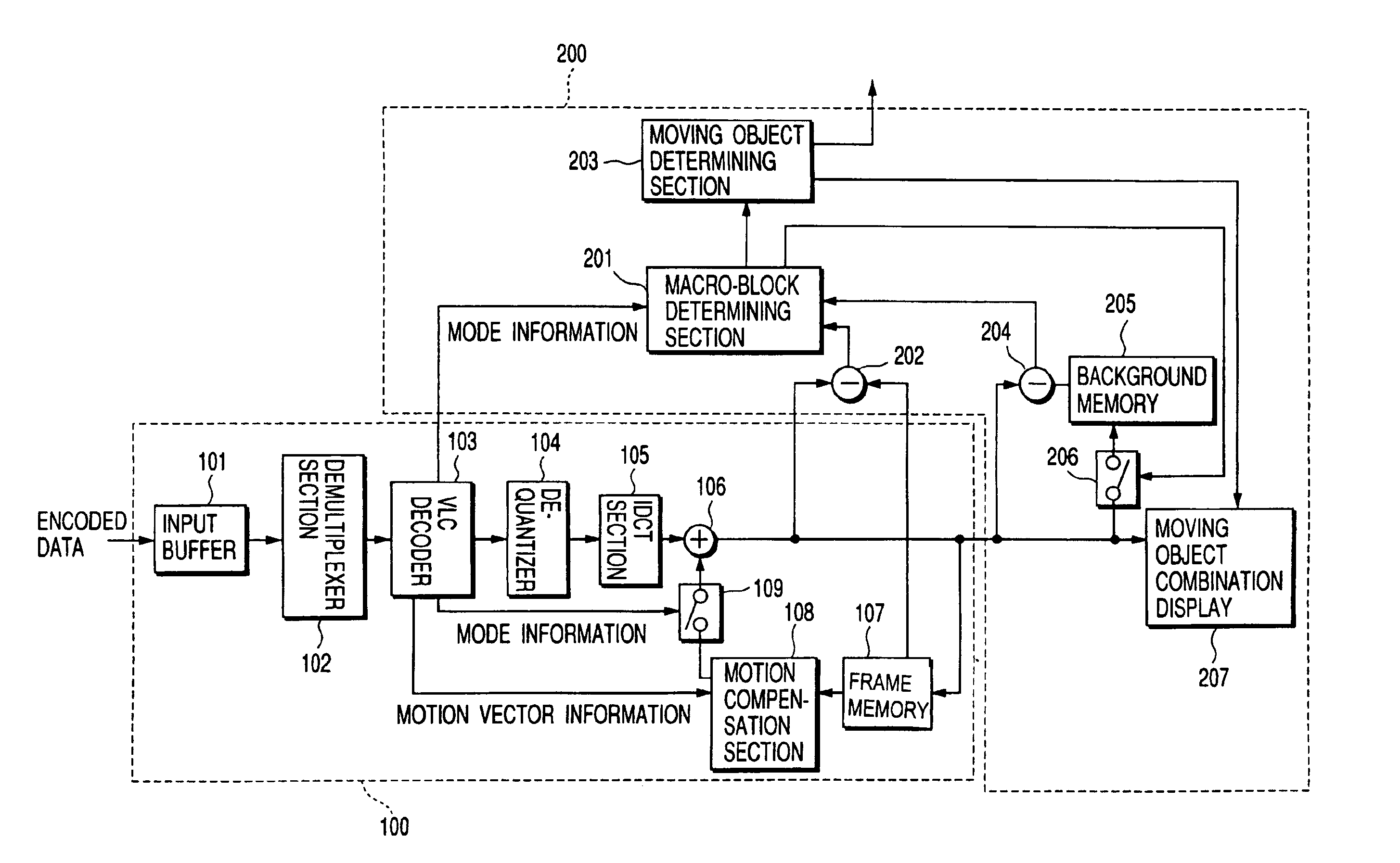
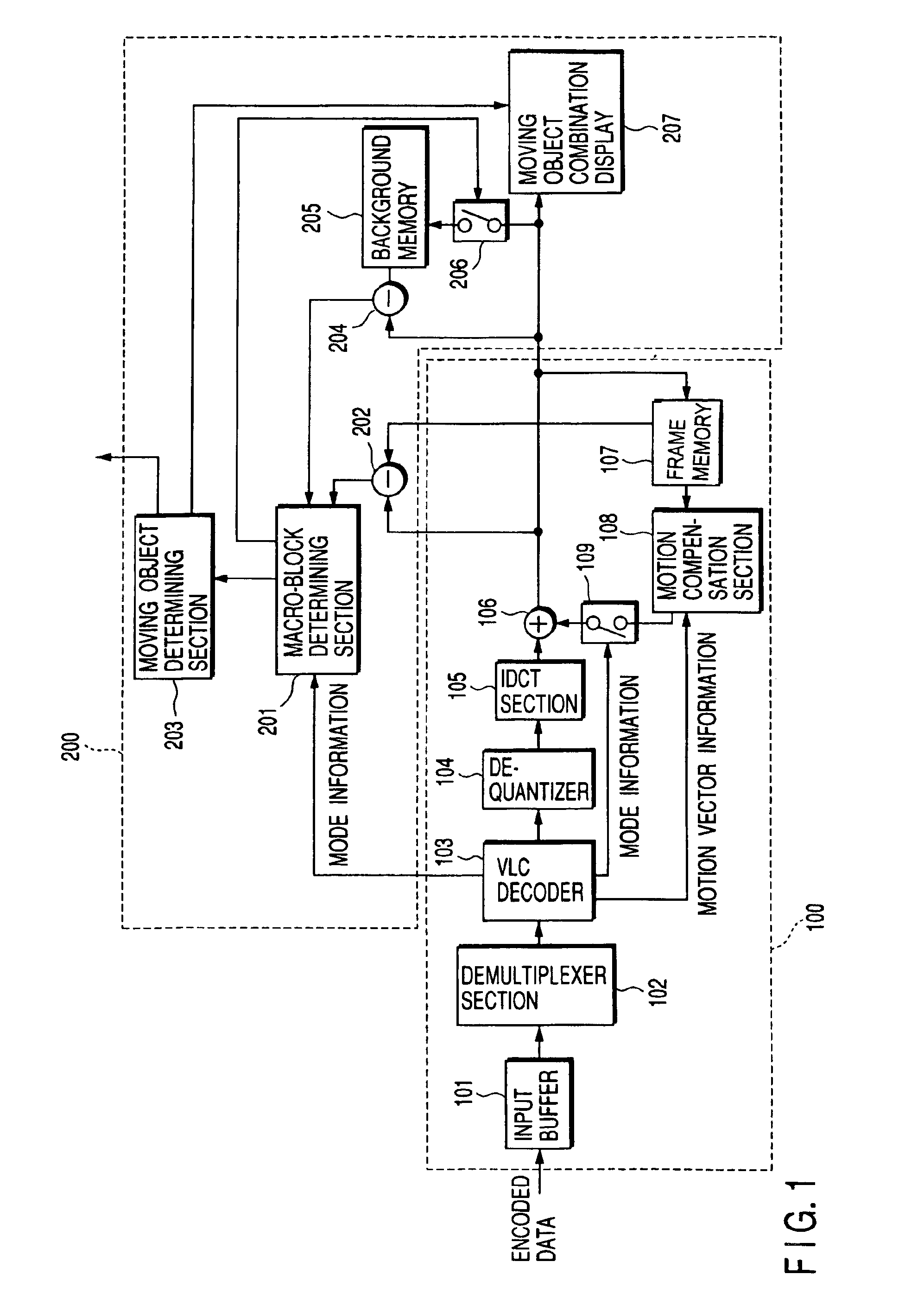
FIG. 1 is a block diagram illustrating the structure of a video moving object detecting apparatus according to one embodiment of this invention. This video moving object detecting apparatus comprises a video decoder section 100 and a moving object detector section 200, which will be discussed below in order. The following description is given of the case where this invention is adapted to a video moving object detecting apparatus based on the MPEG system and a unit area of a reconstructed video signal is equivalent to a macro-block in the MPEG system.

Video Decoder Section 100

The video decoder section 100 is a video decoder based on, for example, the MPEG system, or a so-called MPEG decoder. Encoded data which is obtained by compression-encoding in a video encoder (not shown), such as an MPEG encoder, is input to the video decoder section 100 over a transmission channel o...


PUM


Abstract

An apparatus for detecting a moving object in motion video comprises a macro-block determining section for determining the background / non-background of each macro-block of a reconstructed video signal from a video decoder section which decodes encoded data obtained by compression-encoding a motion video signal, a moving object determining section for determining an area of the moving object from the result of the determination on the background / non-background, and a moving object combination display for displaying information indicating the area of the moving object on a display screen for the reconstructed video signal. The macro-block determining section determines if a macro-block represents a background area or a non-background area, based on mode information from the video decoder section and a cross correlation value between a present frame of the reconstructed video signal and a signal of a frame preceding the present frame by one frame, obtained by a first cross correlation calculator, and a cross correlation value between the present frame of the reconstructed video signal and a background video signal stored in a background memory, obtained by a second cross correlation calculator.

Description

CROSS-REFERENCE TO RELATED APPLICATIONSThis application is based upon and claims the benefit of priority from the prior Japanese Patent Application No. 11-248851, filed on Sep. 2, 1999, the entire contents of which are incorporated herein by reference.BACKGROUND OF THE INVENTIONThe present invention relates to a method for detecting a moving object in motion video and an apparatus therefor, and, more particularly, to a method for detecting a moving object in motion video from the output of a video decoder and an apparatus therefor.To detect a moving object present in motion video, it is generally necessary to check the motion of each pixel image. But, the pixel-by-pixel motion checking actually requires a vast amount of computation. In the case of the CIF format that is often used in H.261 or H.263 in ITU-T which is the international standard for video compression, MPEG-4 or the like of ISO / IEC, for example, it is necessary to detect the motion of each of a huge number of pixel imag...

Claims


Application Information

Patent Timeline
Patent Type & Authority Patents(United States)
IPC IPC(8): G06T7/20H04N7/12H04N11/00H04N11/02H04N19/00H04N19/20H04N19/21H04N19/423H04N19/44H04N19/503H04N19/51H04N19/61H04N19/63H04N19/91
CPCH04N19/23H04N19/503G06T2207/10016G06T2207/20021G06T7/254
Inventor CHUJOH, TAKESHIKIKUCHI, YOSHIHIROSAKUMA, AKIRAHAYASHI, TOSHIFUMIKOBAYASHI, HIROYUKI
Owner KK TOSHIBA
Why Eureka
Try Eureka