Throw-away insert and milling cutter using throw-away insert

a technology of throwaway inserts and milling cutters, which is applied in the direction of metal-working equipment, metal-working apparatus, milling equipment, etc., can solve the problems of reducing the dimensional accuracy after sintering, the change of dimensions is unavoidable, and the cutting accuracy and attachment accuracy are inferior when attaching to the cutter body, so as to improve the dimensional accuracy and shape accuracy, reduce density variations, and maintain the stability of the axial suppor

Active Publication Date: 2007-08-28
SUMITOMO ELECTRIC HARDMETAL CORP
View PDF13 Cites 12 Cited by
  • Summary
  • Abstract
  • Description
  • Claims
  • Application Information

AI Technical Summary

Benefits of technology

[0015]In the insert of the present invention, the corner angles of the four nose sections are essentially right angles when seen from above, allowing powder to fill these nose sections easily. As a result, the conditions under which the powder fills the nose sections are uniform, allowing the powder to fill uniformly and reducing density variations. This restricts variations in dimensional changes (deformations) during sintering, thus improving dimensional accuracy and shape accuracy.
[0016]Also, the axial support surface of the insert is formed as a section of the end surface, and this axial support surface is provided at a position independent from the secondary cutting section. Thus, the area of the axial support surface is not reduced even if the secondary cutting section is damaged. This maintains the stability of axial support. As a result, cutting is made more stable and accurate, and increased support load caused by reduction in the area is prevented, thus improving the tool life of the insert and the cutter body.
[0017]Furthermore, the presence of the secondary cutting section, which cleans the bottom surface of the cut corner, improves the surface roughness of the bottom surface.

Problems solved by technology

During sintering, changes in dimensions are unavoidable.
The inserts obtained by sintering this type of shaped body have reduced dimensional accuracy after sintering, resulting in inferior cutting accuracy and attachment accuracy when attaching to a cutter body.
This reduces the dimensional accuracy after sintering.
However, since the ridge line axially projected from the end of the body is used as the secondary cutting section and since the sloped surface forming the secondary cutting section is used to axially support the insert, the small area of the sloped surface is further reduced when the secondary cutting section is damaged, leading to reduced axial support stability.

Method used


Image

  • Throw-away insert and milling cutter using throw-away insert
  • Throw-away insert and milling cutter using throw-away insert
  • Throw-away insert and milling cutter using throw-away insert

Examples


Embodiment Construction

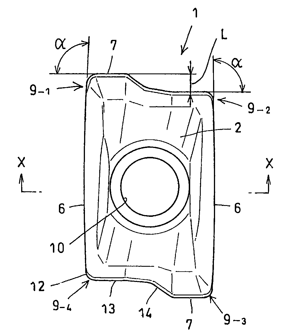
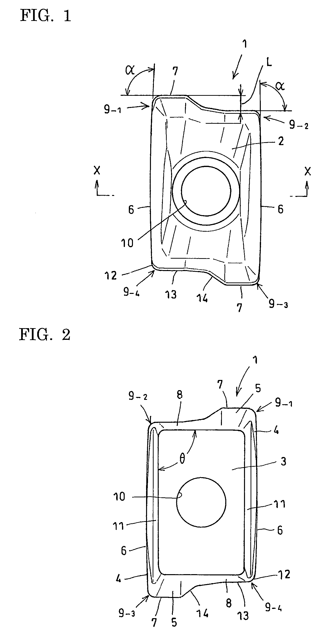
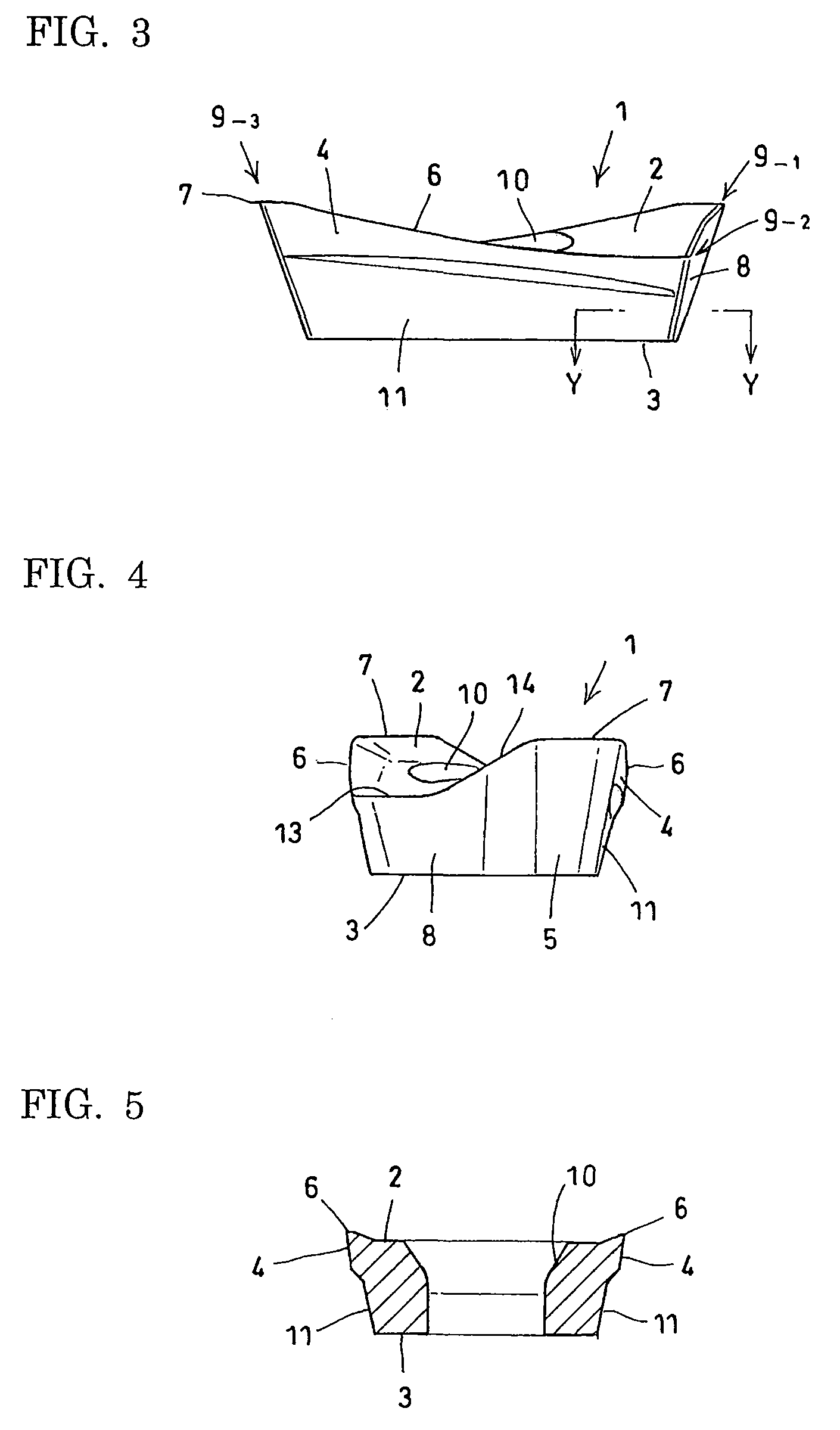
[0030]Referring to FIG. 1 through FIG. 6, an embodiment of a throw-away insert according to the present invention will be described. A throw-away insert 1 shown in the figure includes: an upper surface 2; a flat, roughly rectangular bottom surface 3 formed with four corners; two side surfaces 4, 4 continuous with two parallel sides of the bottom surface 3; two end surfaces 5, 5 continuous with the other two parallel sides of the bottom surface 3; two long main cutting sections 6, 6; two secondary cutting section 7, 7 provided at two opposing corners; an axial support surface 8 supported by an insert pocket of a cutter body; four nose sections 9-1-9-4 formed at the corners of the upper surface 2; an insert hole 10 for clamping; and a radial support surface 11 formed on the lower sides of side surfaces 4, 4.

[0031]In the insert of this example, a height difference is present on the upper surface 2. In the upper surface 2, the nose sections 9-1, 9-3, which are at diagonal corners, have ...


PUM

PropertyMeasurementUnit
corner anglesaaaaaaaaaa
angleaaaaaaaaaa

Abstract

A throw-away insert includes: an upper and bottom surface; two side surfaces; two end surfaces; a main cutting section formed from a ridge line positioned at the intersection between the side surfaces and the upper surface; a secondary cutting section formed from a ridge line positioned at the intersection between the end surfaces and the upper surface; an axial support surface supported by an insert pocket of a cutter body; and noses formed at the corners of the upper surface. The corner angles of the noses when seen from above are essentially right angles. The axial support surface is formed as a section of the end surface. The secondary cutting section is parallel to the ridge line at the upper end of the axial support surface and the bottom surface. The upper end of the axial support surface is positioned so that it is projected more in the direction of the longitudinal axis of the main cutting section than the ridge line of the upper end.

Description

INCORPORATION BY REFERENCE[0001]The present application claims priority under 35 U.S.C. §119 to Japanese Patent Application No. 2005-229573 filed on Aug. 8, 2005. The content of the application is incorporated herein by reference in its entirety.BACKGROUND OF THE INVENTION[0002]1. Field of the Invention[0003]The present invention relates to a throw-away insert used in the milling of right-angle corners and the like and a milling cutter, e.g., an end mill or corner mill, that uses this insert.[0004]2. Description of the Background Art[0005]Japanese Utility Model Publication Number 2531557 and Japanese Laid-open Patent Publication Number Hei 11-333616 describes an example of a throw-away insert (also referred to below simply as insert) used with a negative / positive orientation to cut right-angle corners. Negative / positive orientation refers to mounting an insert so that a radial rake of the insert is negative and the axial rake is positive.[0006]The insert described in Japanese Utilit...

Claims


Application Information

Patent Timeline
Patent Type & Authority Patents(United States)
IPC IPC(8): B23C5/20
CPCB23C5/109B23C5/202B23C2200/083B23C2200/123B23C2200/125Y10T407/23B23C2200/286Y10T407/1908Y10T407/1924Y10T407/1936B23C2200/203
Inventor MAEDA, KAZUO
Owner SUMITOMO ELECTRIC HARDMETAL CORP
Why Eureka
Try Eureka