Network time protocol precision timestamping service

a technology of time protocol and time stamp, applied in the field of network time protocol precision timestamping service, can solve the problems of compromising the correct correction of the client clock, propagating to the client clock, and introducing errors in the timestamp provided by the ntp server, so as to avoid the uncertainty of device drivers, improve the control and improve the accuracy of the timetamping function

Active Publication Date: 2013-05-28
IP GEM GRP LLC
View PDF13 Cites 13 Cited by
  • Summary
  • Abstract
  • Description
  • Claims
  • Application Information

AI Technical Summary

Benefits of technology

[0011]One advantage of the disclosed systems and methods is that improved control of the timestamping function may be implemented in the existing NTP servers without the risk of introducing interworking incompatibilities with other servers and clients that are compliant with the current NTP standards. Importantly, the disclosed methods include steps that utilize the packet timestamping engine and the latency estimator filter in a manner that retains compatibility with the current NTP standards. In this fashion, the time-of-arrival and time-of-departure are detected and registered by hardware, thereby achieving high degree of precision, and the uncertainty associated with the device drivers, network stacks, operating system, and so on is avoided. As a result, more accurate and stable NTP server timestamps are provided to the NTP client.

Problems solved by technology

However, despite the high accuracy of the hardware based clock at the NTP server, if there are any inaccuracies associated with the timestamping function in the NTP server, the NTP server introduces errors into the timestamps provided to the client.
Subsequently, these errors propagate to the client clock and compromise proper correction of the client clock.
Consequently, inaccurate receive and transmit timestamps propagate from the NTP system 100 to the client clock and set the baseline error for time keeping and rate keeping at the client clock.

Method used


Image

  • Network time protocol precision timestamping service
  • Network time protocol precision timestamping service
  • Network time protocol precision timestamping service

Examples


Embodiment Construction

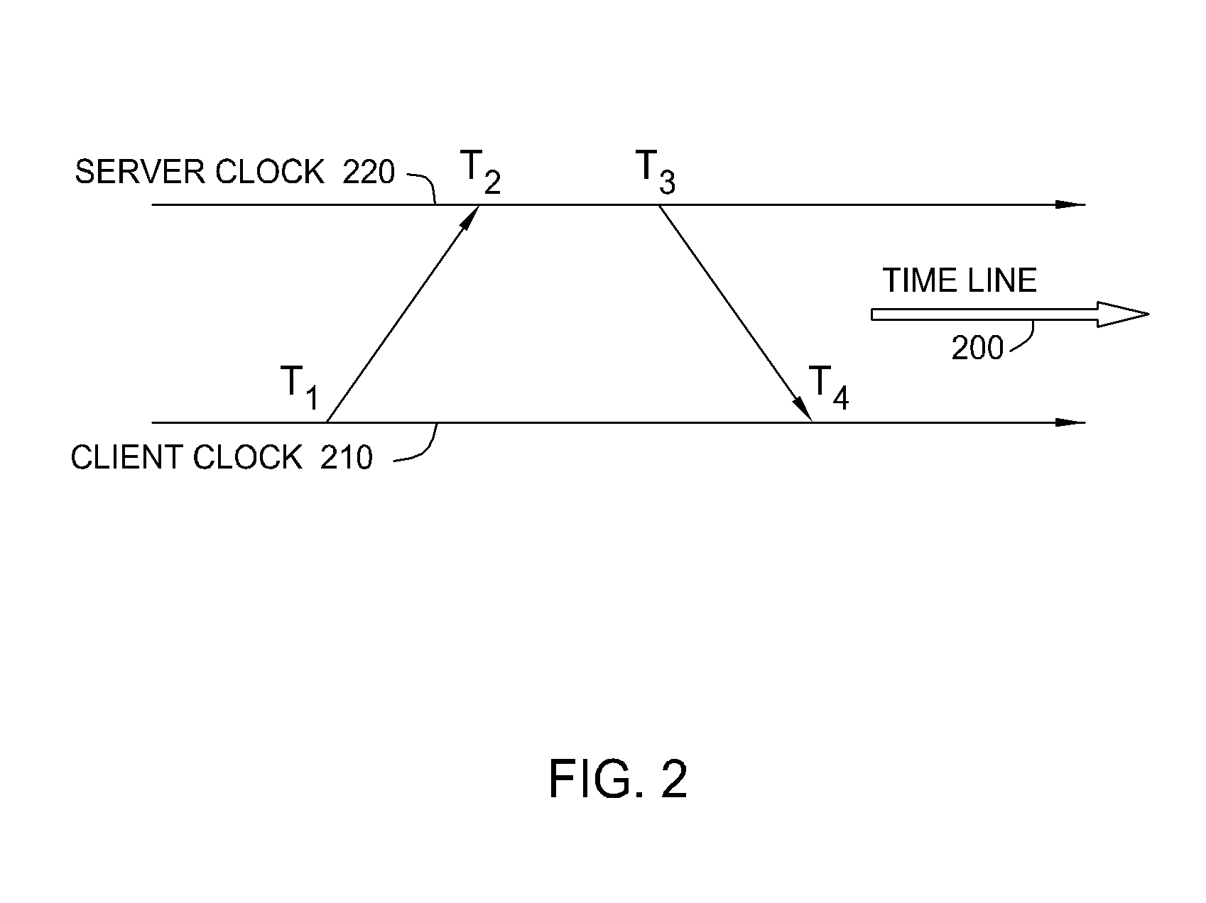
[0019]FIG. 2 illustrates timestamps contained in a header of an NTP packet, according to one embodiment of the present invention. As shown in FIG. 2, each time measurement along a time line 200 involves four timestamps, which are defined as follows: T1 is a timestamp representing the best estimate of the transmit originating epoch of a packet originating from a client clock 210, T2 is a timestamp representing the best estimate of the receive termination epoch of a packet terminating at a precision NTP server clock 220, T3 is a timestamp representing the best estimate of the transmit origination epoch of a packet originating from the precision NTP server clock 220, and T4 is a timestamp representing the best estimate of the receive termination epoch of a packet terminating at the client clock 210. After the time measurement, these four timestamps are used to calculate the roundtrip delay between the endpoints and the offset of the client clock 210 according to the following principle...


PUM


Abstract

Embodiments of the present invention set forth a method and system for reducing uncertainty in receive and transmit timestamps created by an NTP server. The uncertainty in the receive timestamps is removed by recording the time-of-arrival in the hardware clock of the NTP server before the incoming packets may be delayed by traversing the various layers of software in a timestamping system. The uncertainty in the transmit timestamps is removed by giving the outgoing packets a timestamp in the future using an estimate of the transmission latency calculated by the latency estimator filter. Subsequently, the actual time-of-departure is used to re-calculate and update the estimate of the transmission latency. In this fashion, superior control of the timestamping function may be implemented in existing NTP servers in a manner that retains interworking compatibility with the current NTP standards.

Description

BACKGROUND OF THE INVENTION[0001]1. Field of the Invention[0002]Embodiments of the present invention generally relate to improving the time-offset accuracy between the transmitter and receiver paths over data networks and, more specifically, to network time protocol precision timestamping service.[0003]2. Description of the Related Art[0004]In many communications applications, each element in a network has its own internal clock running independently of the other clocks in the network. Where the networks are synchronous networks, such as in many telecommunications applications and in high speed wide area networks, these clocks must be synchronized to the server. In legacy telecommunications networks, network elements utilized “TDM” links, such as T1 and SONET, which are inherently capable of carrying timing information from server to client at the physical layer. However, it is generally agreed that next generation networks will be based on a packet-switched infrastructure and, ther...

Claims


Application Information

Patent Timeline
Patent Type & Authority Patents(United States)
IPC IPC(8): H04L7/00H04J3/06H04J3/07H04L7/02
CPCH04J3/0673H04J3/0697H04L69/28H04L7/00
Inventor DOWD, GREGORY LOUIS
Owner IP GEM GRP LLC
Why Eureka
Try Eureka