Closed battery and closing member

a closed battery and closing member technology, applied in the field of closed batteries, can solve the problems of battery rupture, battery harm to users, danger of broken devices and batteries, etc., and achieve the sealability high that is required for non-aqueous batteries

Inactive Publication Date: 2002-07-23
TOYO KOHAN CO LTD +1
View PDF6 Cites 13 Cited by
  • Summary
  • Abstract
  • Description
  • Claims
  • Application Information

AI Technical Summary

Problems solved by technology

Such a complex closed battery has a merit of storability, but has the disadvantage in that its high sealability sometimes causes rupture of the battery itself due to the abnormally elevated internal pressure thereof in cases where the battery is exposed to high temperature, or a short circuit is formed inside or outside of the battery to cause a large flow of the current, or hydrogen gas is generated in the battery due to water contamination during in the manufacturing process thereof.
In such a case,

Method used


Image

  • Closed battery and closing member
  • Closed battery and closing member
  • Closed battery and closing member

Examples


Embodiment Construction

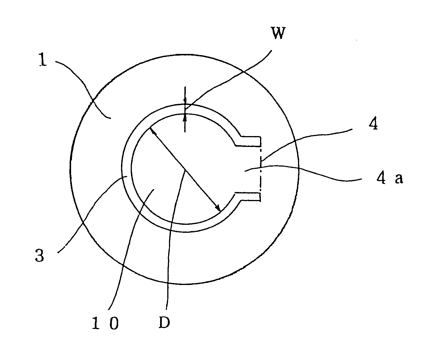
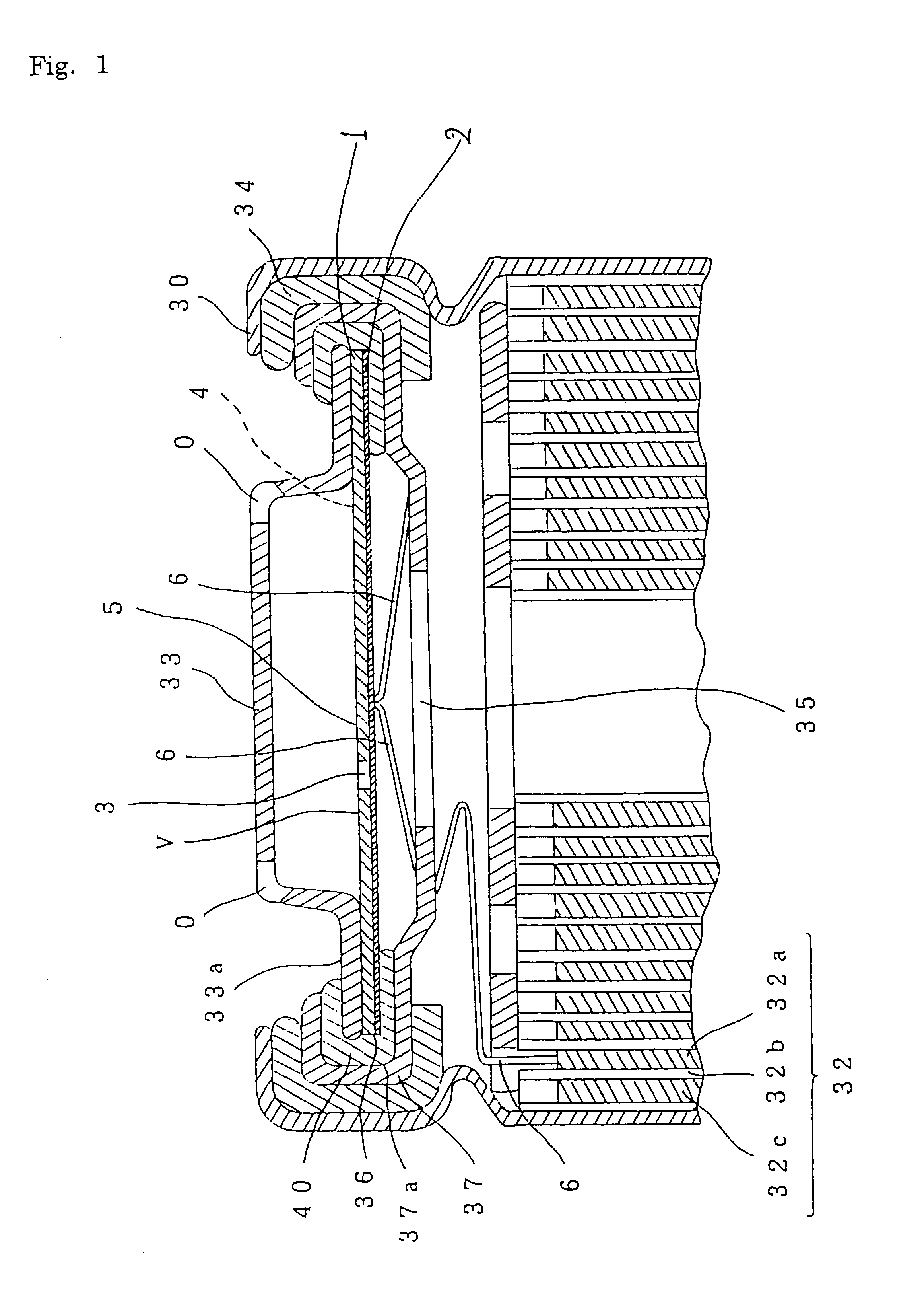
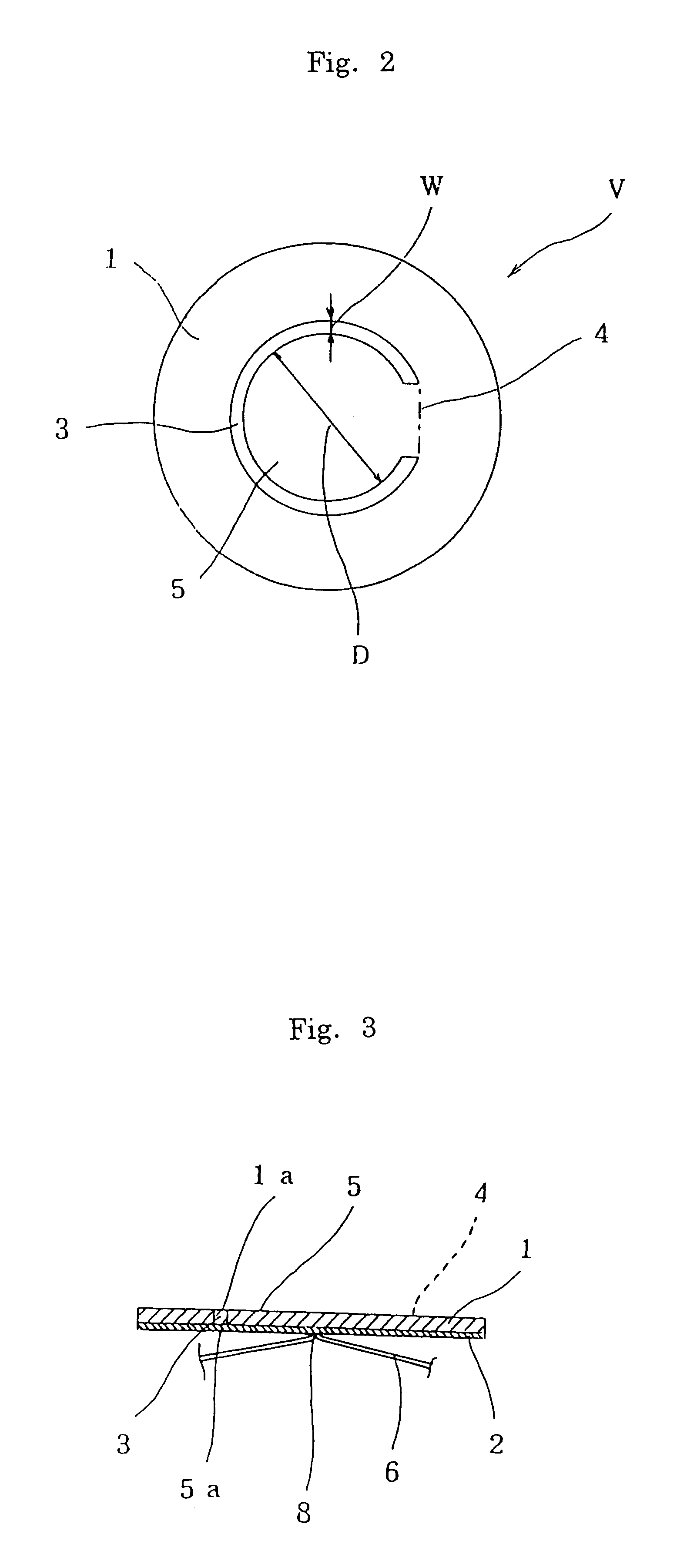
The present invention is now explained in conjunction with preferred embodiments and examples referring to the drawings. FIG. 1 is a vertical section view showing an upper part of a completely closed battery of the present invention. FIG. 2 is a plane view showing a valve chip of the closed battery of the present invention. FIG. 3 is a vertical section view showing the above mentioned valve chip. FIG. 4 and FIG. 5 are explanatory views showing operating manners of the valve chip in case of abnormality. FIG. 6 and FIG. 7 are plane views showing other embodiments of the valve chip.

In FIG. 1, a cylindrical battery container 30 having a bottom, which serves as a negative electrode terminal, accommodates an electrode element 32 together with an electrolyte which is isolated from the outside. The electrode element 32 is constituted of a coiled laminate which comprises a positive electrode 32a, a separator 32b, and a negative electrode 32c disposed opposite to the positive electrode 32a vi...


PUM


Abstract

The object of the present invention is to provide a closed battery capable of rapidly releasing the internal pressure thereof and at the same time disconnecting the current to effectively prevent itself from temperature rising and exploding so that in such a completely closed battery it may assure the safety and reliability thereof, when the internal pressure is elevated due to short circuit, overcharge, reverse charge, or the like. A valve element 5 is provided with a slit 3 between the circumference thereof and a metal substrate 1. When the internal pressure of a battery is elevated, the valve element 5 is smoothly raised up together with a metal foil 2 from a bending fulcrum portion 4 to thereby cut a lead wire 6 or permit a braze portion 8 to detach from the lead wire 6, thus disconnecting the current reliably. Then, the metal foil which usually closes the slit formed around the circumference of the valve element 5 is allowed to burst stably and accurately at a prescribed pressure to thereby form a valve opening portion 7 so that the internal gas of the battery can be discharged.

Description

1. Field of the InventionThe present invention relates to a closed battery capable of bursting at a prescribed pressure, especially at a low pressure, to rapidly release the internal pressure and at the same time to break the current, when the temperature or internal pressure of the battery is elevated, and to a closing member for use in the closed battery.2. Prior ArtRecently, with increasing requirement of electronic devices that are made much smaller in size, light weight and have enhanced performance, the use of non-aqueous batteries with high energy density has become popular. Batteries which use an alkaline metal such as lithium, sodium, or potassium as an active material of negative electrode thereof employ battery containers of completely closed structure because the alkaline metal easily acts with water.Such a complex closed battery has a merit of storability, but has the disadvantage in that its high sealability sometimes causes rupture of the battery itself due to the abn...

Claims


Application Information

Patent Timeline
IPC IPC(8): H01M2/34H01M2/20H01M2/12H01M50/574
CPCH01M2/1241H01M2/34H01M2/345Y02E60/10H01M50/3425H01M50/578H01M50/574
Inventor TAKADA, AKIYOSHISAIJO, KINJIYOSHIDA, KAZUOYOSHIMOTO, NOBUYUKIISOBE, YOSHIHIKO
Owner TOYO KOHAN CO LTD
Why Eureka
Try Eureka