Ink jet head and ink jet printer capable of preventing variation of a volume of an ink droplet due to cross talk

a technology of ink jet printer and ink droplet, which is applied in the direction of printing, inking apparatus, etc., can solve the problems of non-uniform density or deterioration of image quality in printed matter, and achieve the effect of preventing the occurrence of non-uniform density or deterioration of image quality

Active Publication Date: 2006-03-28
TOSHIBA TEC KK
View PDF11 Cites 5 Cited by
  • Summary
  • Abstract
  • Description
  • Claims
  • Application Information

AI Technical Summary

Benefits of technology

[0015]Accordingly, an object of the present invention is to provide an ink jet head and an ink jet printer capable of preventing a variation of a volume of an ink droplet ejected from each ejecting nozzle caused by a crosstalk, thereby being capable of preventing the occurrence of a non-uniform density or deterioration in image quality.

Problems solved by technology

However, the above-mentioned shear mode ink jet head has a problem that a phenomena so-called crosstalk occurs in which a pressure fluctuation in some pressure chamber gives a fluctuation in a pressure or a flow velocity of the ink in the other nearby pressure chamber.
This leads to a difference between a volume of the ink droplet ejected from an ejecting nozzle communicating with the pressure chambers positioned at both sides within the printing range and a volume of an ink droplet ejected from an ejecting nozzle communicating with the pressure chambers positioned at the inside of the printing range, thereby being likely to cause a non-uniform density or a deterioration in image quality in a printed matter.

Method used


Image

  • Ink jet head and ink jet printer capable of preventing variation of a volume of an ink droplet due to cross talk
  • Ink jet head and ink jet printer capable of preventing variation of a volume of an ink droplet due to cross talk
  • Ink jet head and ink jet printer capable of preventing variation of a volume of an ink droplet due to cross talk

Examples


Embodiment Construction

)

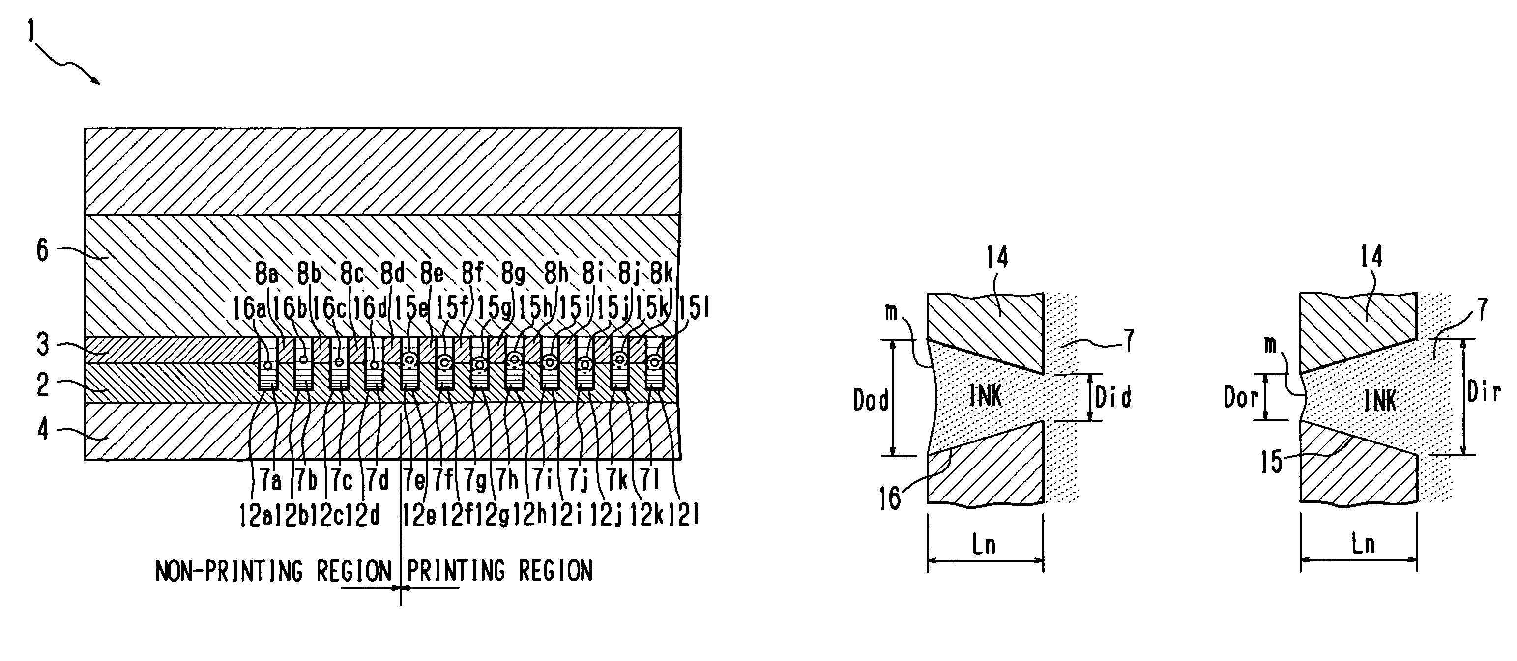
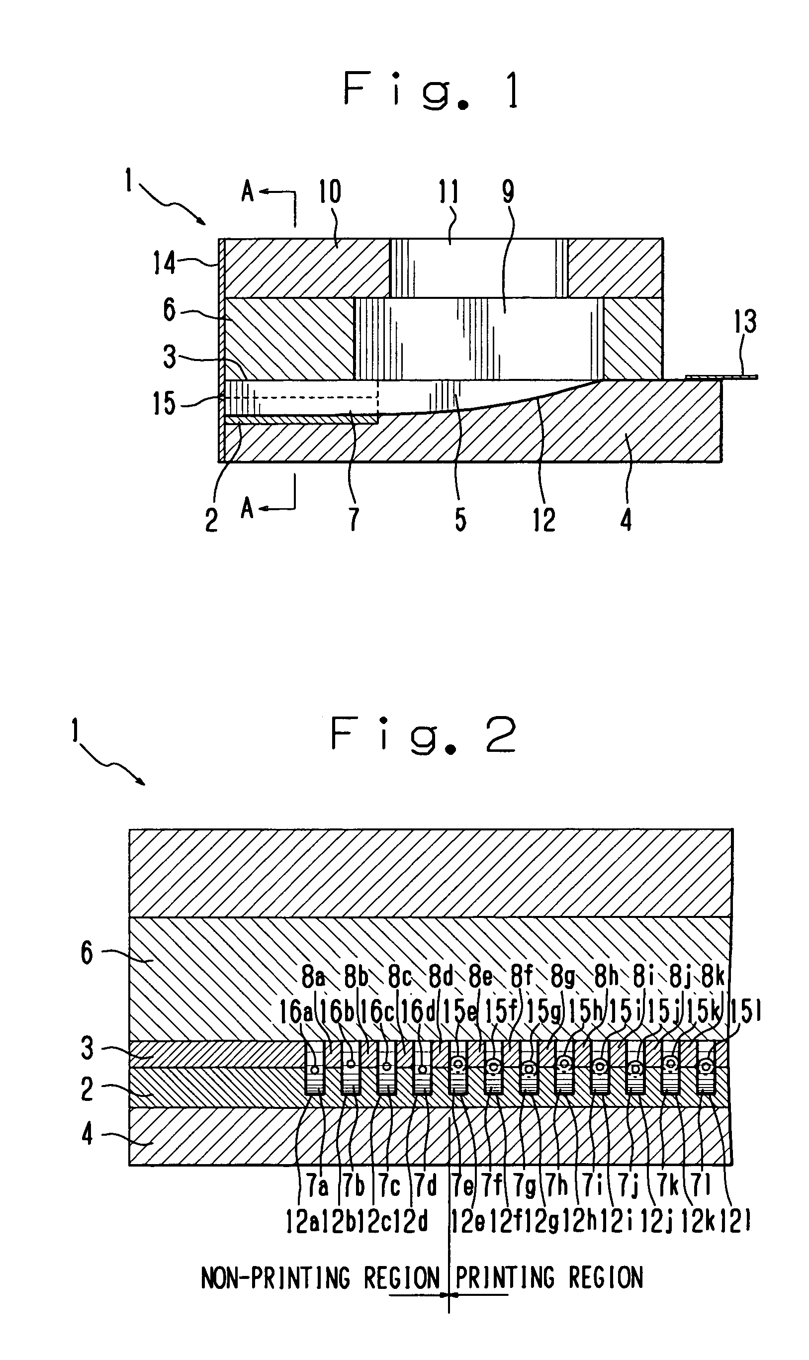
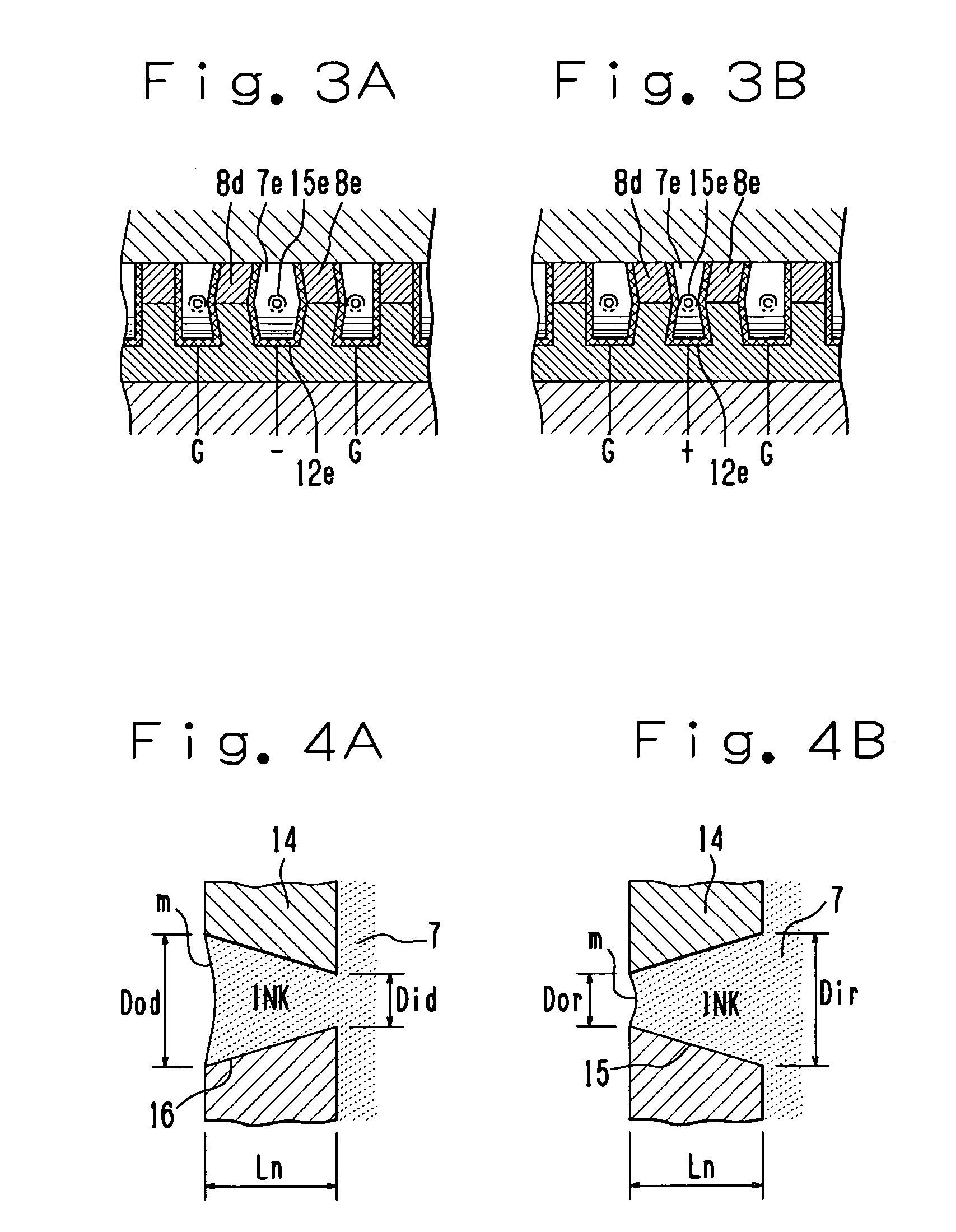
[0033]An embodiment of the present invention will be explained with reference to FIGS. 1 to 8. FIG. 1 is a longitudinal side view showing an ink jet head, while FIG. 2 is a sectional view taken along a line A—A in FIG. 1.

[0034]The ink jet head 1 in the present embodiment is provided with two piezoelectric members (lower piezoelectric member 2 and upper piezoelectric member 3) polarized in a direction of a plate thickness as shown in FIGS. 1 and 2. Two piezoelectric members 2 and 3 are laminated with the same polarity opposed to each other. The laminated piezoelectric members 2 and 3 are fixed to a substrate 4 made of a non-polarized low dielectric constant piezoelectric member.

[0035]The substrate and the piezoelectric members 2 and 3 fixed to this substrate 4 have plural channels 5 arranged in parallel with the same space. The plural channels 5 are processed by using a diamond cutter or the like.

[0036]A top plate frame 6 is adhered on the top surface of the substrate 4. This top pl...


PUM


Abstract

An ink jet head that varies a capacity in each of plural pressure chambers arranged in parallel, each of which is defined by side walls, each communicating with an ink supplying path, for ejecting an ink droplet from an ejecting nozzle mounted at one end of this pressure chamber is provided with a dummy nozzle that is provided at one end of the pressure chamber positioned at the non-printing region and is set to have an aperture diameter at the ink ejecting side greater than an aperture diameter of the ejecting nozzle and to have a flow impedance approximately same as that of the ejecting nozzle. When the ink droplet is ejected from the ejecting nozzle communicating with the pressure chamber positioned at the end section within the printing region, the capacity in the pressure chamber positioned at the non-printing region is varied simultaneous with the variation of the capacity in the pressure chamber positioned at the end section within the printing region, thereby preventing a variation in volume of the ink droplet ejected from each ejecting nozzle caused by a crosstalk and preventing the occurrence of a non-uniform density or deterioration in image quality.

Description

CROSS REFERENCE TO RELATED APPLICATION[0001]The present application is based on Japanese Priority Document JP2002-353233 filed on Dec. 5, 2002 the content of which is incorporated herein by reference.BACKGROUND OF THE INVENTION[0002]1. Field of the Invention[0003]The present invention relates to an ink jet head and an ink jet printer performing an image formation by ejecting an ink droplet.[0004]2. Discussion of the Background[0005]In a conventional technique, a shear mode ink jet head has been well-known as disclosed in U.S. Pat. No. 4,879,568 wherein a capacity in a pressure chamber is varied by pressure means that produces a shear strain in accordance with an electrical signal for selectively ejecting ink from an ejecting nozzle provided at each pressure chamber, thereby performing an image formation. This type of shear mode ink jet head has a characteristic that the pressure chamber is easy to be arranged with high density.[0006]However, the above-mentioned shear mode ink jet he...

Claims


Application Information

Patent Timeline
Patent Type & Authority Patents(United States)
IPC IPC(8): B41J2/14B41J2/16B41J2/045
CPCB41J2/04581B41J2/04588B41J2/14209B41J2/1433B41J2/04595B41J2202/20
Inventor KUSUNOKI, RYUTARO
Owner TOSHIBA TEC KK
Why Eureka
Try Eureka