
Mandibular advancer and method of installing the same

a mandibular advancer and advancer technology, applied in the field of mandibular advancer and method of installation, can solve the problems of affecting the patient's facial appearance and the growth of the nose, and achieve the effect of enhancing occlusal support and enhancing occlusal suppor

Inactive Publication Date: 2006-03-28
CLARK WILLIAM J
View PDF6 Cites 12 Cited by
  • Summary
  • Abstract
  • Description
  • Claims
  • Application Information

AI Technical Summary

Benefits of technology

[0014]All or at least a portion of the casting form occlusal surface may be contoured to account for orthodontic conditions other than a Class II or III malocclusion. For instance, all or part of the casting form occlusal surface may be recessed a certain degree to account for what is known as a “deep bite” orthodontic condition (e.g., to present a concave surface). In addition, all or part of the casting form occlusal surface may be bulged a certain degree or the casting form may have an enhanced occlusal-gingival extent to account for what is known as an “open bite” orthodontic condition.
[0039]Enhancement of the interconnection between the crown and the crown mandibular advancement incline frame may be realized by incorporating at least one, and more preferably a plurality of, apertures which extend through the entire occlusal-gingival extent of the first frame section. At least one of these apertures may be disposed so as to expose a portion of the crown occlusal surface on which the first frame section overlies. Polymerized material may occupy the entire extent of any such apertures. At least one aperture may also be disposed on that portion of the first frame section which extends beyond the crown occlusal surface. This may facilitate the directing of polymerizable material within the space defined between the first and second frame sections. Polymerizable material may be captured within this space between the first and second frame sections by having a pair of extensions which project from the opposite sides of the first frame section at least toward the “free” end of the second frame section or an apex of the second frame section.

Problems solved by technology

The disadvantage of this approach is that the nose continues to grow, when the maxilla is retracted, and the nose becomes unduly prominent in the profile, while the maxilla and mandible are retracted to a retrusive position.
This approach may align the anterior teeth, but at the same time, is detrimental to the patient's facial appearance.

Method used


Image

  • Mandibular advancer and method of installing the same
  • Mandibular advancer and method of installing the same
  • Mandibular advancer and method of installing the same

Examples


Embodiment Construction

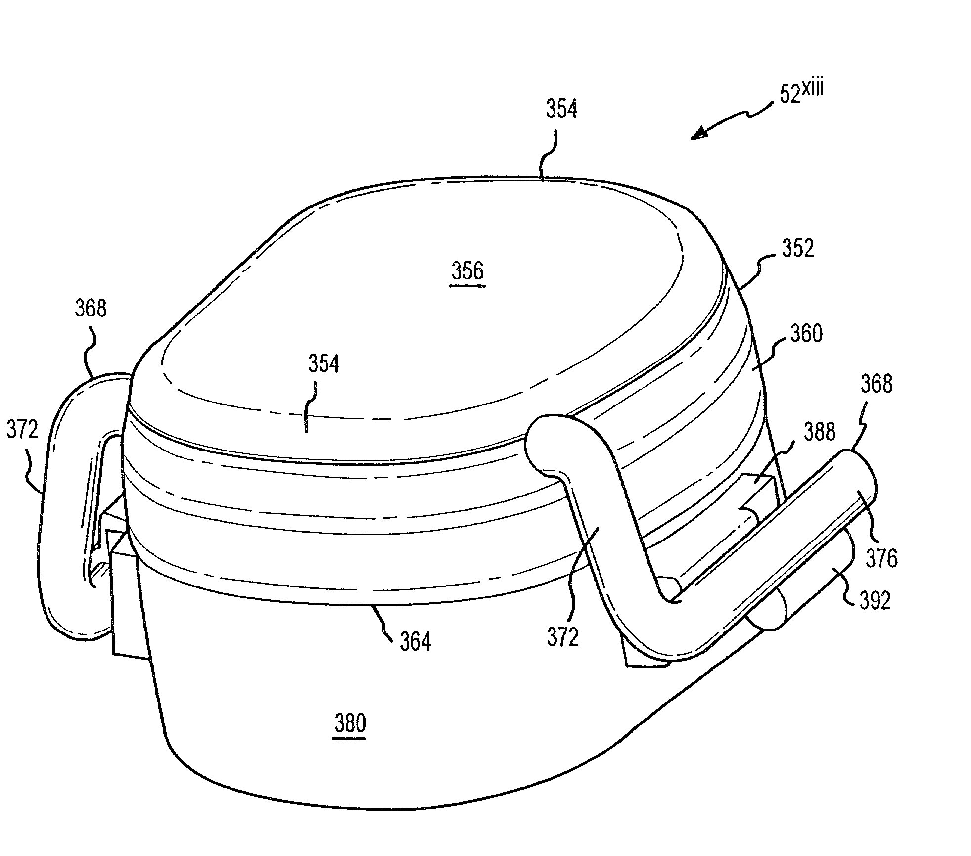
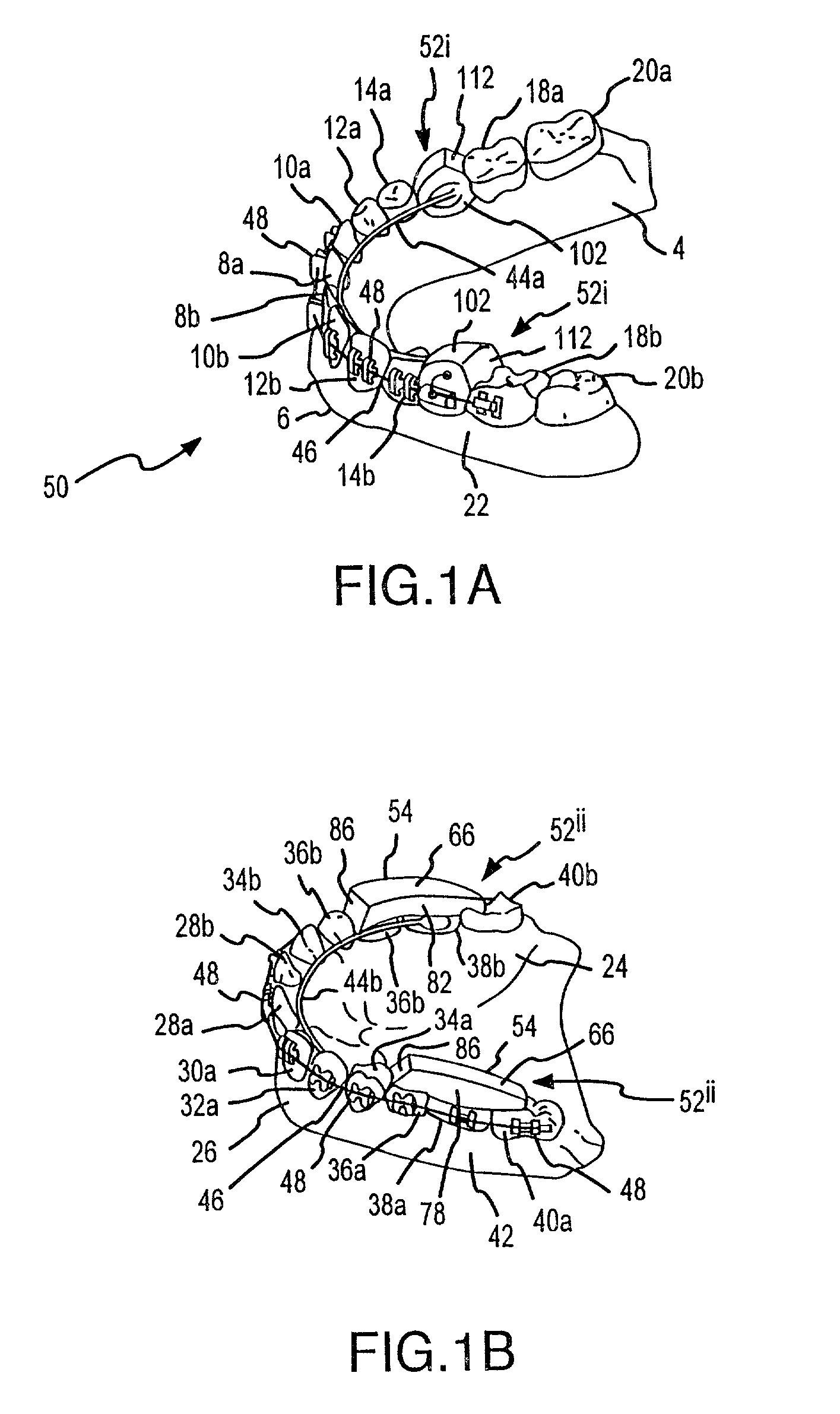
[0083]The present invention will now be described in relation to the accompanying drawings which at least assist in illustrating its various pertinent features. FIGS. 1A–B illustrate a mandible 4 and maxilla 24 of a patient. The mandible 4 includes a lower dental arch 6 having two sides—one side using an “a” designation for its corresponding teeth and with the opposite side using a “b” designation for its corresponding teeth. Each side of the lower dental arch 6 includes the following teeth which extend from a lower gingiva 22 of the patient: a lower central 8, a lower lateral 10, a lower cuspid 12, a lower first bicuspid 14, a lower second bicuspid 16, a lower first molar 18, and a lower second molar 20. The maxilla 24 includes an upper dental arch 26 having two sides—one side using an “a” designation for its corresponding teeth and with the opposite side using a “b” designation for its corresponding teeth. Each side of the upper dental arch 26 includes the following teeth which ex...


PUM


Abstract

Multiple embodiments of mandibular advancers are disclosed. Advancement of the mandible is affected by mounting such an mandibular advancer on each side of both the upper dental arch and the lower dental arch. One embodiment of such an mandibular advancer includes a casting form with a rigid polymerized material therein and which includes a casting form mandibular advancement incline formed on an end thereof. The casting form mandibular advancement incline may wear away in certain instances to expose the polymerized material therebeneath which has been cured and assumed the shape of this casting form mandibular advancement incline. Other embodiments of such mandibular advancers include a crown or a band, each of which has a mandibular advancement incline as a part thereof (e.g., integrally, via separate attachment). Certain of these crowns or the band with a mandibular advancement incline associated therewith may be disposed within the above-noted casting form and encapsulated within the noted polymerized material. Preferably this disposes the mandibular advancement incline associated with the crown / band in interfacing relation with the casting form mandibular advancement incline.

Description

CROSS-REFERENCE TO RELATED APPLICATIONS[0001]This patent application claims priority from and is a continuation of U.S. patent application Ser. No. 09 / 648,086, which is entitled “MANDIBULAR ADVANCER AND METHOD OF INSTALLING THE SAME,” which was filed on Aug. 25, 2000, and now U.S. Pat. No. 6,368,106, which claims priority from and is a continuation-in-part of U.S. patent application Ser. No. 09 / 559,792, which is entitled “MANDIBULAR ADVANCER AND METHOD OF INSTALLING THE SAME,” and which was filed on Apr. 27, 2000 (abandoned), which claims priority from and is a continuation-in-part of U.S. patent application Ser. No. 09 / 533,892, which is entitled “MANDIBULAR ADVANCER AND METHOD FOR ASSEMBLING THE SAME,” and which was filed on Mar. 22, 2000 (abandoned). Priorty is being claimed to each of the noted applications.FIELD OF THE INVENTION[0002]The present invention generally relates to the field of the advancement of the mandible or lower jaw in typically an orthodontic treatment setting ...

Claims


Application Information

Patent Timeline
IPC IPC(8): A61C3/00A61C7/00A61C7/36
CPCA61C7/36A61C7/00
Inventor CLARK, WILLIAM J.
Owner CLARK WILLIAM J
Learn More